Short description
| Bus controller | OPC UA FX |
General information
| B&R ID code | 0xF629 |
| Status indicators | Module status, bus function |
| Diagnostics | |
| Module status | Yes, using LED status indicator and software |
| Bus function | Yes, using LED status indicator and software |
| Power consumption | |
| Bus | 3.5 W |
| Additional power dissipation caused by actuators (resistive) [W] | - |
| Certifications | |
| CE | Yes |
| UKCA | Yes |
| EAC | Yes |
Interfaces
Electrical properties
| Electrical isolation | OPC UA FX isolated from bus and I/O |
Operating conditions
| Mounting orientation | |
| Horizontal | Yes |
| Vertical | Yes |
| Installation elevation above sea level | |
| 0 to 2000 m | No limitation |
| >2000 m | Reduction of ambient temperature by 0.5°C per 100 m |
| Degree of protection per EN 60529 | IP20 |
Ambient conditions
| Temperature | |
| Operation | |
| Horizontal mounting orientation | -25 to 45°C |
| Vertical mounting orientation | -25 to 40°C |
| Derating | See section "Derating". |
| Storage | -40 to 85°C |
| Transport | -40 to 85°C |
| Relative humidity | |
| Operation | 5 to 95%, non-condensing |
| Storage | 5 to 95%, non-condensing |
| Transport | 5 to 95%, non-condensing |
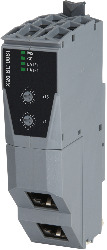
Materialnummer:
X20BC008TBeskrivning:
- Communication technology: OPC UA Field eXchange (FX)
- I/O configuration via OPC UA FX
- 400 µs minimum cycle time
- Integrated switch for daisy-chaining
- 2x 1 Gbit/s full-duplex mode
- OPC UA diagnostics and module diagnostics at runtime via OPC UA clients
This bus controller provides OPC UA FX functions. This allows any OPC UA clients access to read or write data from I/O modules connected to the bus controller.
Obligatoriska tillbehör
System modules for bus controllers
| X20BB80X | X20 bus controller base for X20BC008T and X20 power supply module, X20 end cover plates (left and right) X20AC0SL1/X20AC0SR1 included |
| X20PS9400 | X20 power supply module, for bus controller and internal I/O power supply X2X Link power supply |
| X20PS9402 | X20 power supply module, for bus controller and internal I/O power supply, X2X Link supply, supply not galvanically isolated |
Terminal blocks
| X20TB12 | X20 terminal block, 12-pin, 24 VDC keyed |
| Certifikat | Version (datum) | Ladda ner |
|---|---|---|
| EU Declaration ATEX X20 | PDF / 218 KB | |
| EU Declaration of conformity PLC X20 | PDF / 169 KB | |
| UK Declaration PLC X20 | PDF / 151 KB |
| Dokumentation | Version (datum) | Ladda ner |
|---|---|---|
| Data sheet X20BC008T | PDF / 6 MB | |
| Installation- / EMC-Guide | PDF / 20 MB | |
| X20 System User´s Manual | PDF / 7 MB |
| E-CAD (Electro eller EPLAN mallar) | Version (datum) | Ladda ner |
|---|---|---|
| X20 EPLAN P8 from V2.4 | EXE / 160 MB |
| M-CAD (Mechan. mallar) | Version (datum) | Ladda ner |
|---|---|---|
| 3D File STEP/DXF X20BC and X20IF Module | ZIP / 1 MB |
| Mjukvaruuppdateringar | Version (datum) | Ladda ner |
|---|---|---|
| Firmwareupgrade X20BC008T | ZIP / 63 MB |