Short description
| Communication module | 1 M-Bus master for controlling up to 64 slaves |
General information
| Diagnostics | |
| Module run/error | Yes, using LED status indicator and software |
| Data transfer | Yes, using LED status indicator |
| M-Bus power supply | Yes, using LED status indicator and software |
| Power consumption | |
| Bus | 0.2 W |
| Internal I/O | 0.35 W + (Number of slaves * 0.08 W) |
| Certifications | |
| CE | Yes |
| UKCA | Yes |
| CRA (Cyber Resilience Act) | In preparation |
| ATEX |
Zone 2, II 3G Ex nA nC IIA T5 Gc IP20, Ta (see X20 user's manual) FTZÚ 09 ATEX 0083X |
| UL |
cULus E115267 Industrial control equipment |
| HazLoc |
cCSAus 244665 Process control equipment for hazardous locations Class I, Division 2, Groups ABCD, T5 |
| B&R ID code | 0xCABF |
| Status indicators | Data transfer, M-Bus power supply, operating state, module status |
| Module power dissipation | 0.55 W + (Number of slaves * 0.006 W) |
| Additional power dissipation caused by actuators (resistive) [W] | - |
| Insulation voltage between M-Bus and X2X Link | 500 VDC, 1 min |
Interfaces
Electrical properties
| Electrical isolation |
M-Bus isolated from bus M-Bus not isolated from I/O power supply
|
Operating conditions
| Mounting orientation | |
| Horizontal | Yes |
| Vertical | Yes |
| Installation elevation above sea level | |
| 0 to 2000 m | No limitation |
| >2000 m | Reduction of ambient temperature by 0.5°C per 100 m |
| Degree of protection per EN 60529 | IP20 |
Ambient conditions
| Temperature | |
| Operation | |
| Horizontal mounting orientation | -25 to 60°C |
| Vertical mounting orientation | -25 to 50°C |
| Derating | - |
| Storage | -40 to 85°C |
| Transport | -40 to 85°C |
| Relative humidity | |
| Operation | 5 to 95%, non-condensing |
| Storage | 5 to 95%, non-condensing |
| Transport | 5 to 95%, non-condensing |
Mechanical properties
| Note |
Order 1x terminal block X20TB12 separately. Order 1x bus module X20BM11 separately. |
| Pitch | 12.5+0.2 mm |
Materiaalnummer:
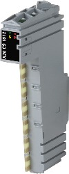
X20CS1012Omschrijving:
- Power supply for up to 64 slaves on the M-Bus
- Decentralized use of the communication interface
The M-Bus master is designed as a single-width module and can be connected anywhere within the X20 I/O system. It can therefore be used decentrally for distributed topologies. The M-Bus master supports transfer rates of 300, 2400 and 9600 bit/s; up to 64 slaves supplied via M-Bus can be connected.
M-Bus (Meter-Bus) is a relatively simple fieldbus for recording consumption data, such as from electricity or heat meters. It is based on a reverse polarity protected two-wire line and works according to the master-slave principle.
Vereiste toebehoren
| Automation Studio HW Upgrades | Versie (Datum) | Download |
|---|---|---|
| V2.7 HW Upgrade (X20CS1012) | EXE / 2 MB | |
| V3.0 HW Upgrade (X20CS1012) | EXE / 4 MB | |
| V4.0 HW Upgrade (X20CS1012) | EXE / 2 MB |
| Documentatie | Versie (Datum) | Download |
|---|---|---|
| Data sheet X20CS1012 | PDF / 1 MB | |
| X20 Package leaflet ATEX/CSA | PDF / 2 MB | |
| X20 System User´s Manual | PDF / 49 MB |
| E-CAD (Electro of EPLAN Templates) | Versie (Datum) | Download |
|---|---|---|
| X20 EPLAN P8 from V2.4 | EXE / 160 MB |
| M-CAD (Mechan. Templates) | Versie (Datum) | Download |
|---|---|---|
| 3D File DXF/STEP X20 Electronic module | ZIP / 10 KB | |
| 3D File STEP X20 I/O-Slice | ZIP / 872 KB | |
| Dimensions PDF X20 Electronic module | PDF / 3 KB |