Short description
| I/O module | 8 digital outputs 11.5 to 30 V with 1-wire connections |
General information
| Diagnostics | |
| Module run/error | Yes, using LED status indicator and software |
| Outputs | Yes, using software |
| Power consumption | |
| Bus | 0.16 W |
| External I/O | 0.2 W |
| Certifications | |
| CE | Yes |
| UKCA | Yes |
| CRA (Cyber Resilience Act) | In preparation |
| ATEX |
Zone 2, II 3G Ex nA nC IIA T5 Gc IP20, Ta (see X20 user's manual) FTZÚ 09 ATEX 0083X |
| UL |
cULus E115267 Industrial control equipment |
| HazLoc |
cCSAus 244665 Process control equipment for hazardous locations Class I, Division 2, Groups ABCD, T5 |
| B&R ID code | 0xDF4E |
| Status indicators | Operating state, module status |
| Additional power dissipation caused by actuators (resistive) [W] | - |
Digital outputs
Electrical properties
| Electrical isolation |
Channel isolated from bus Channel not isolated from channel and I/O power supply |
Operating conditions
| Mounting orientation | |
| Horizontal | Yes |
| Vertical | Yes |
| Installation elevation above sea level | |
| 0 to 2000 m | No limitation |
| >2000 m | Reduction of ambient temperature by 0.5°C per 100 m |
| Degree of protection per EN 60529 | IP20 |
Ambient conditions
| Temperature | |
| Operation | |
| Horizontal mounting orientation | -25 to 60°C |
| Vertical mounting orientation | -25 to 50°C |
| Derating | - |
| Storage | -40 to 85°C |
| Transport | -40 to 85°C |
| Relative humidity | |
| Operation | 5 to 95%, non-condensing |
| Storage | 5 to 95%, non-condensing |
| Transport | 5 to 95%, non-condensing |
Mechanical properties
| Note |
Order 1x terminal block X20TB12 separately. Order 1x bus module X20BM11 separately. |
| Pitch | 12.5+0.2 mm |
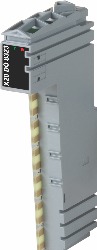
Référence produit:
X20DO8323Description:
- 8 digital outputs
- High-side or low-side connection
- Push/pull outputs
- 1-wire connections
- Integrated output protection
The module is an electrically isolated 8-channel digital output module. It can be configured as high-side or low-side or as a push/pull output for controlling 12 to 24 VDC DC motors.
Accessoires obligatoires
Bus modules
| X20BM11 | X20 digital output module, 8 outputs, 12 to 24 V, 0.5 A, sink/source, 1-wire connections, full bridge, half bridge, thermal overload protection |
| X20BM15 | X20 digital output module, 8 outputs, 12 to 24 V, 0.5 A, sink/source, 1-wire connections, full bridge, half bridge, thermal overload protection |
Terminal blocks
| X20TB12 | X20 digital output module, 8 outputs, 12 to 24 V, 0.5 A, sink/source, 1-wire connections, full bridge, half bridge, thermal overload protection |
| Automation Studio HW Upgrades | Version (date) | Téléchargement |
|---|---|---|
| V3.0 HW Upgrade (X20DO8323) | EXE / 1 Mo | |
| V4.0 HW Upgrade (X20DO8323) | EXE / 627 Ko |
| Documentation | Version (date) | Téléchargement |
|---|---|---|
| Data sheet X20DO8323 | PDF / 762 Ko | |
| X20 Package leaflet ATEX/CSA | PDF / 2 Mo | |
| X20 System User´s Manual | PDF / 49 Mo |
| E-CAD (modèles Electro ou EPLAN) | Version (date) | Téléchargement |
|---|---|---|
| X20 EPLAN P8 from V2.4 | EXE / 160 Mo |
| M-CAD (modèles mécaniques) | Version (date) | Téléchargement |
|---|---|---|
| 3D File DXF/STEP X20 Electronic module | ZIP / 10 Ko | |
| 3D File STEP X20 I/O-Slice | ZIP / 872 Ko | |
| Dimensions PDF X20 Electronic module | PDF / 3 Ko |