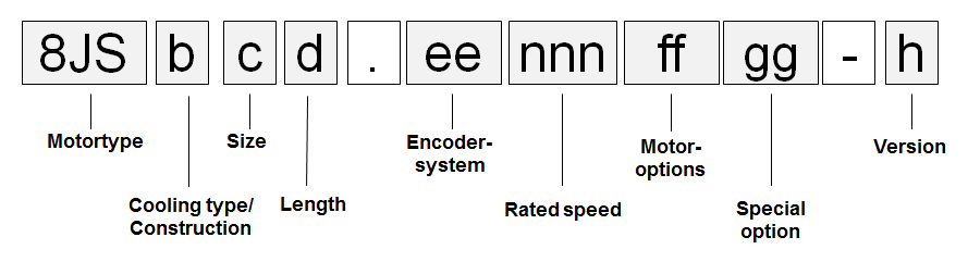
Cooling / construction type (b)
Cooling / construction type (b)
Cooling type A
8JS three-phase synchronous motors with cooling type A are self-cooling and have a long, slim design. The motors must be installed on the cooling surface (flange).
Size (c)
Size (c)
8JS three-phase synchronous motors are available in six different sizes (2 through 7). They have different dimensions (especially flange dimensions) and power ratings. These different sizes are indicated by a number represented by (c) in the model number. The larger the number, the larger the flange dimensions and power rating for the respective motor.
Overview
Cooling type | Available sizes | |||||
|---|---|---|---|---|---|---|
2 | 3 | 4 | 5 | 6 | 7 | |
A | Yes | Yes | Yes | Yes | Yes | Yes |
Length (d)
Length (d)
8JS three-phase synchronous motors are available in up to five different lengths. They have different power ratings with identical flange dimensions. These different lengths are indicated by a number represented by (d) in the model number.
Overview
Length | Available sizes | |||||
|---|---|---|---|---|---|---|
2 | 3 | 4 | 5 | 6 | 7 | |
1 | --- | Yes | --- | Yes | --- | --- |
2 | Yes | Yes | Yes | Yes | Yes | Yes |
3 | --- | Yes | Yes | --- | Yes | Yes |
4 | Yes | --- | Yes | Yes | Yes | Yes |
5 | --- | --- | --- | --- | Yes | --- |
Encoder system (ee)
Encoder system (ee)
Resolver
General information
BRX resolvers are used in the servo motors. These resolvers are fed with a single sinusoidal signal (reference signal) and return two sinusoidal signals. The amplitude of these signals change with the angular position (sine or cosine form).
Technical data
Name | Order code (ee) |
|---|---|
R0 | |
Accuracy | 10 angular minutes |
Vibration during operation | ≤ 100 m/s² |
Shock during operation | ≤ 400 m/s² |
EnDat encoders
General information
EnDat is a standard developed by Johannes Heidenhain GmbH (www.heidenhain.de) that incorporates the advantages of absolute and incremental position measurement while also offering a read/write parameter memory in the encoder. With absolute position measurement (the absolute position is sampled serially), a homing procedure for referencing is usually not required. Where necessary, a multi-turn encoder (4096 revolutions) should be installed. To save costs, a single-turn encoder and a reference switch can also be used. In this case, a homing procedure must be carried out. The incremental process allows the short deceleration periods necessary for position measurement when using drives with highly dynamic characteristics. With the sinusoidal incremental signal and the fine resolution in the EnDat module, a very high positioning resolution is achieved in spite of the moderate signal frequencies used.
Technical data
Different types of EnDat 2.1 encoders can be used depending on requirements:
Name | ||||||||
|---|---|---|---|---|---|---|---|---|
E4 1) | E5 1) | E6 2) | E7 2) | E8 1) | E9 1) | EA 2) | EB 2) | |
Encoder type | EnDat single-turn | EnDat multi-turn | EnDat single-turn | EnDat multi-turn | EnDat single-turn | EnDat multi-turn | EnDat single-turn | EnDat multi-turn |
Operating principle | Optical | Optical | Optical | Optical | Inductive | Inductive | Inductive | Inductive |
EnDat protocol | EnDat 2.1 | EnDat 2.1 | EnDat 2.1 | EnDat 2.1 | EnDat 2.1 | EnDat 2.1 | EnDat 2.1 | EnDat 2.1 |
Resolution | 512-line | 512-line | 2048-line | 2048-line | 16-line | 16-line | 32-line | 32-line |
Recognizable revolutions | --- | 4096 | --- | 4096 | --- | 4096 | --- | 4096 |
Accuracy | ±60" | ±60" | ±20" | ±20" | ±480" | ±480" | ±180" | ±180" |
Cutoff frequency | ≥ 200 kHz (-3 dB) | ≥ 200 kHz (-3 dB) | ≥ 400 kHz (-3 dB) | ≥ 400 kHz (-3 dB) | ≥ 6 kHz (-3 dB) | ≥ 6 kHz (-3 dB) | ≥ 6 kHz (-3 dB) | ≥ 6 kHz (-3 dB) |
Vibration during operation3) 55 < f ≤ 2000 Hz | ≤ 100 m/s² | ≤ 100 m/s² | ≤ 150 m/s² | ≤ 150 m/s² | ≤ 300 m/s² | ≤ 300 m/s² | ≤ 200 m/s² | ≤ 200 m/s² |
Shock during operation4) Duration 6 ms | ≤ 1000 m/s² | ≤ 1000 m/s² | ≤ 1000 m/s² | ≤ 1000 m/s² | ≤ 1000 m/s² | ≤ 1000 m/s² | ≤ 2000 m/s² | ≤ 2000 m/s² |
Manufacturer Internet address | Dr. Johannes Heidenhain GmbH www.heidenhain.de | |||||||
Manufacturer's product ID | ECN1113 | EQN1125 | ECN1313 | EQN1325 | ECI1118 | EQI1130 | ECI1319 | EQI1331 |
| 1) | Only available for size 2 and 3 motors. |
| 2) | Only available for size 4, 5, 6 and 7 motors. |
| 3) | In accordance with IEC 60 068-2-6 |
| 4) | In accordance with IEC 60 068-2-27 |
Rated speed (nnn)
Rated speed (nnn)
8JSA three-phase synchronous motors can be delivered with different nominal speeds depending on the size and length.
Size | Lengths | ||||
|---|---|---|---|---|---|
1 | 2 | 3 | 4 | 5 | |
2 | --- | 8000 | --- | 8000 | --- |
3 | 5000 | 3000, 5500 | 4500 | --- | --- |
4 | --- | 3500 | 5000 | 4000 | --- |
5 | 4500 | 4500 | --- | 2750, 5000 | --- |
6 | --- | 3000 | 2250 | 3000 | 2500 |
7 | --- | 2000 | 2400 | 1800 | --- |
Oil seal (ff)
Oil seal (ff)
All 8JSA three-phase synchronous motors are available with an optional Form A oil seal in accordance with DIN 3760.
When equipped with an oil seal, the motors have IP65 protection in accordance with EN 60034-5.
Proper lubrication of the oil seal must be ensured throughout the entire service life of the motor.
Holding brake (ff)
Holding brake (ff)
All 8JSA three-phase synchronous motors can be delivered with a holding brake. It is installed directly behind the B bearing on the motor and used to hold the motor shaft when no power is applied to the servo motor.
Operating principle
The holding brake is a spring-loaded brake and is controlled by the ACOPOS servo drive or an ACOPOSmulti inverter module. Based on principle, this type of holding brake exhibits a minimal amount of backlash.
This brake is designed as a holding brake and is not permitted to be used for operational braking! Under these conditions, the brake has a service life of approximately 5,000,000 cycles (opening and closing the brake is one cycle). Loaded braking during an emergency stop is permitted but reduces its service life. The required brake holding torque is determined based on the actual load torque. If not enough information is known about the load torque, it is recommended to assume a safety factor of 2.
Technical data for the standard holding brake
Name | Motor size | |||||
|---|---|---|---|---|---|---|
2 | 3 | 4 | 5 | 6 | 7 | |
Holding torque MBr [Nm] | 1.42 | 2.5 | 5.3 | 14.5 | 25 | 53 |
Connected load Pon [W] | 8.4 ±7% | 10.1 ±7% | 12.8 ±7% | 19.5 ±7% | 25.7 ±7% | 35.6 ±7% |
Supply current Ion [A] | 12:35 AM | 12:42 AM | 12:53 AM | 0.82 | 1.07 | 1:48 AM |
Installed voltage Uon [V] (+6% / -10%) | 24 VDC | 24 VDC | 24 VDC | 24 VDC | 24 VDC | 24 VDC |
Moment of inertia JBr [kgcm²] | 0,011 | 0,011 | 0,068 | 0,173 | 0.61 | 1.64 |
Mass mBr [kg] | 12:27 AM | 12:35 AM | 0.63 | 1.1 | 2 | 2.9 |
Shaft end (ff)
Shaft end (ff)
All 8JSA three-phase synchronous motor shafts comply with DIN 748 and are available with a smooth shaft end.
Smooth shaft end
A smooth shaft end is used for a force-fit shaft-hub connection and guarantees a backlash-free connection between the shaft and hub as well as a high degree of operating smoothness. The end of the shaft has a threaded center hole.
Keyed shaft end
A keyed shaft end is used for a form-fit torque transfer with low demands on the shaft-hub connection and for handling torque in a constant direction.
The keyways for the 8JS three-phase synchronous motors conform to keyway form N1 per DIN 6885-1. Form A keyed shafts that conform to DIN 6885-1 are used. Balancing motors with keyways is done using the shaft and fitment key convention per ISO 1940/1, G6.3.
The end of the shaft has a threaded center hole that can be used to mount machine actuators with shaft end cover plates.
Special motor options (gg)
Special motor options (gg)
00...No special motor options
Motor version (h)
Motor version (h)
The motor version is automatically specified by the configurator and can be seen in the technical data.
Order code motor options (ff)
The respective code (ff) for the order key can be found in the following table:
Motor option | ||||
|---|---|---|---|---|
Connectiondirection | Oil seal | Holding brake | Shaft end | Code for the order key (ff) |
Angled (swivel connector) | No | No | Smooth | D0 |
Keyed | D1 | |||
Normal | Smooth | D2 | ||
Keyed | D3 | |||
Yes | No | Smooth | D6 | |
Keyed | D7 | |||
Normal | Smooth | D8 | ||
Keyed | D9 | |||
Reduction of rated values depending on the motor option
The nominal values are reduced depending on the motor option selected (stall torque M0 and nominal torque Mn) for the motor as seen in the following table: (all values in [Nm])
Motor | Holding brake | EnDat encoders | Holding brakes and EnDat encoders | Oil seal |
|---|---|---|---|---|
8JSA22.eennnffgg-0 | 0.01 | 0 | 0.02 | 0.047 |
8JSA24.eennnffgg-0 | 0.05 | 0 | 0.12 | 0.047 |
8JSA31.eennnffgg-0 | 0 | 0 | 0 | 0.047 |
8JSA32.eennnffgg-0 | 0.05 | 0 | 0.1 | 0.047 |
8JSA33.eennnffgg-0 | 0.1 | 0 | 0.2 | 0.047 |
8JSA42.eennnffgg-0 | 0.12 | 0.1 | 0.36 | 0.071 |
8JSA43.eennnffgg-0 | 0.12 | 0.2 | 0.55 | 0.071 |
8JSA44.eennnffgg-0 | 0.12 | 0.3 | 0.76 | 0.071 |
8JSA51.eennnffgg-0 | 0.15 | 0.15 | 0.39 | 0.13 |
8JSA52.eennnffgg-0 | 0.26 | 0.34 | 0.76 | 0.13 |
8JSA54.eennnffgg-0 | 0.43 | 0.86 | 1.55 | 0.13 |
8JSA62.eennnffgg-0 | 0.5 | 0.9 | 1.6 | 0.25 |
8JSA63.eennnffgg-0 | 0.9 | 1.2 | 2.4 | 0.25 |
8JSA64.eennnffgg-0 | 1.3 | 1.5 | 3.1 | 0.25 |
8JSA65.eennnffgg-0 | 1.7 | 1.8 | 4 | 0.25 |
8JSA72.eennnffgg-0 | 1 | 2 | 3.9 | 0.25 |
8JSA73.eennnffgg-0 | 1 | 2.7 | 5.1 | 0.25 |
8JSA74.eennnffgg-0 | 1 | 3.4 | 6.2 | 0.25 |
Example Order 1
Example Order 1
A three-phase synchronous motor (type 8JSA44) with a nominal speed of 4000 rpm was selected for an application. The motor should also be equipped with a holding brake, a keyed shaft and a 2048-line EnDat single-turn encoder.
The code (ee) for the encoder system is E6.
The code (nnn) for a nominal speed of 2000 rpm is 040.
The code (ff) for the other options (oil seal, holding brake, keyed shaft and connection direction) is D3.
The model number for the necessary motor is therefore 8JSA44.E6040D300-0.
Example Order 2
Example Order 2
A three-phase synchronous motor (type 8JSA54) with a nominal speed of 5000 rpm was selected for an application. The motor should also be equipped with a holding brake, a smooth shaft, an oil seal and a 2048-line EnDat multi-turn encoder.
The code (ee) for the encoder system is E7.
The code (nnn) for a nominal speed of 2000 rpm is 050.
The code (ff) for the other options (oil seal, holding brake, keyed shaft and connection direction) is D8.
The model number for the necessary motor is therefore 8JSA54.E7050D800-0.