Short description
| I/O module | 8 safe type A digital inputs, 8 pulse outputs, 24 VDC, 4 safe type B1 digital outputs, 24 VDC, 2 A, OSSD <500 µs |
General information
Safety characteristics
| Note | See section "Safety characteristics". |
I/O power supply
| Nominal voltage | 24 VDC |
| Voltage range | 18 to 30 VDC |
| Integrated protective function | Reverse polarity protection |
Safe digital inputs
Safe digital outputs
| Quantity | 4 |
| Variant | FET, 2x positive switching, type B1, output level readable |
| Nominal voltage | 24 VDC |
| Nominal output current | 2 A |
| Total nominal current | 5 A |
| Output protection | See section "Inrush current behavior for output channels". |
| Braking voltage when switching off inductive loads | Max. 45 VDC |
| Error detection time | 1 s |
| Insulation voltage between channel and bus | 500 Veff |
| Peak short-circuit current | See section "Inrush current behavior for output channels". |
| Leakage current when the output is switched off | 100 μA |
| RDS(on) | 250 mΩ |
| Switching voltage | I/O power supply minus voltage drop due to RDS(on) |
| Max. switching frequency | See section "Inrush current behavior for output channels". |
| Test pulse length | Max. 1 ms |
| Max. capacitive load | 100 nF |
| Peak output current | 2.5 A (effective current ≤2 A) |
| Minimum load | 12 mA, hardware revision I0 and later: 0 mA |
Current on loss of ground
| IOUT | <3 mA, hardware revision B2 and later: <1 mA, hardware revision I0 and later: <100 μA |
| IGND | <110 mA |
Pulse outputs
Operating conditions
| Mounting orientation | |
| Any | Yes |
| Installation elevation above sea level | 0 to 2000 m, no limitation |
| Degree of protection per EN 60529 | IP67 |
Mechanical properties
| Dimensions | |
| Width | 53 mm |
| Height | 155 mm |
| Depth | 42 mm |
| Weight | 350 g |
| Torque for connections | |
| M8 | Max. 0.4 Nm |
| M12 | Max. 0.6 Nm |
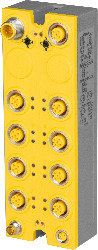
Material number:
X67SC4122.L12Description:
- 8 safe digital inputs, sink circuit
- 8 pulse outputs
- Software input filter configurable for each channel
- 4 safe digital outputs, output type B with 2 A, source circuit
- Node number switches for setting the X2X Link address
- Integrated output protection
The module is equipped with 8 safe digital inputs and 4 safe digital outputs. They are designed for a nominal voltage of 24 VDC.
The module can be used to read in digital signals and to control actuators in safety-related applications up to PL e or SIL 3.
The node number switch for setting the X2X Link address is a unique feature. When modular machine configurations change, it is necessary, for example, to define specific module groups at a fixed address that is independent of the preceding modules in the line. All subsequent standard modules refer to this offset and use it automatically for addressing purposes.
The module is equipped with filters that are individually configurable for switch-on and switch-off behavior. The module also provides pulse signals for diagnosing the sensor line.
The outputs are designed using semiconductor technology so that the safety-related characteristics do not depend on the number of operating cycles. The "high-side high-side" variant (output type B) is required for actuators with reference potential (e.g. Enable inputs on frequency inverters). It is important to observe the special notices for the cabling in this case. Safe digital output channels provide protection against automatic restart when network errors occur.
| Automation Studio HW Upgrades | Version (Date) | Download |
|---|---|---|
| V3.0 HW Upgrade (X67SC4122.L12) | EXE / 3 MB | |
| V4.0 HW Upgrade (X67SC4122.L12) | EXE / 3 MB | |
| V4.6 HW Upgrade (X67SC4122.L12) | EXE / 2 MB | |
| V6.0 HW Upgrade (X67SC4122.L12) | EXE / 558 KB |
| Documentation | Version (Date) | Download |
|---|---|---|
| Data sheets SafeIO and SafeLogic | PDF / 29 MB | |
| Integrated safety technology user's manual | PDF / 59 MB | |
| X67 System User´s Manual | PDF / 19 MB |
| E-CAD (Electro or EPLAN Templates) | Version (Date) | Download |
|---|---|---|
| X67 EPLAN P8 from V2.4 | EXE / 105 MB |
| M-CAD (Mechan. Templates) | Version (Date) | Download |
|---|---|---|
| 3D file DFX/STEP X674122.L12 | ZIP / 2 MB |
| Tools / Utilities / Examples | Version (Date) | Download |
|---|---|---|
| Sistema (VDMA) library | ZIP / 5 KB |