Short description
Interfaces 1x Ethernet, 1x USB, 3x CAN bus, 1x POWERLINK
System module Controller
General information
Insulation voltage for GND and housing 500 Veff
B&R ID code 0xED1F
System requirements
Automation Studio 4.7 or later
Automation Runtime 4.7 or later
mapp Technology Package mapp Safety 5.9.0 and later
Cooling Fanless
Status indicators Controller function, operating state, overtemperature, Ethernet, POWERLINK, safety function
Diagnostics
Module run/error Yes, using LED status indicator and software
CPU function Yes, using LED status indicator
Ethernet Yes, using LED status indicator
Safety function Yes, using LED status indicator
Support
Controller redundancy No
Storage health data support Yes
ACOPOS support Yes
reACTION-capable I/O channels No
Visual Components support Yes
Max. I/O cycle time 2 ms
Power consumption without interface module and USB CPU at Ue = 9 / 32 V: 6.3 / 7.8 W
I/O at Ue = 9 / 32 V: 0.3 / 3.6 W
Certifications
UN ECE-R10 Yes
CE Yes
UKCA Yes
Functional safety IEC 61508:2010
EN 62061:2005/A1:2013
EN ISO 13849-1:2015
EN ISO 13766-2:2018
EN ISO 25119:2018
Safety characteristics
Note See section "Safety characteristics" in data sheet.
Functionality
Support for Safe Commissioning Options
BOOL 64
INT 16
UINT 16
DINT 12
UDINT 12
SafeMOTION support Yes
Max. number of SafeMOTION axes 6, depends on the data width of the modules used
Timing precision Time * 0.05 + Cycle time of the safety application
Max. number of SafeNODEs 10, depends on the data width of the modules used
Data exchange between CPU and SafeLOGIC controller
Max. total data width for each direction 48 bytes
Max. number of data points for each direction
BOOL 128
INT 16
UINT 16
DINT 8
UDINT 8
Data exchange between SafeDOMAIN and SafeDOMAIN
Use as Managing SafeDOMAIN Starting with mapp Safety 5.10.0 and hardware upgrade 2.2.0.0.
Use as Connected SafeDOMAIN Starting with mapp Safety 5.13.0, hardware upgrade 2.3.0.0 and Automation Runtime A4.90
Max. total data width for each direction 8 bytes
Max. total number of data points for each direction 4
Max. number of data points for each direction
BOOL 16
INT 2
UINT 2
DINT 2
UDINT 2
Max. number of linked Managing SafeDOMAINs 0.
Starting with mapp Safety 5.13.0, hardware upgrade 2.3.0.0 and Automation Runtime A4.90: 1
Limit values for SafeDESIGNER application
Max. resources available for SafeDESIGNER info window entries
FB instances 256
Marker memory 5120 bytes (0x1400)
Stack memory 4096 bytes,
version 2.3.0.0 and later. 8192 bytes
Memory for safe input data 128 bytes, 68 bytes of which are usable for modules,
version 2.3.0.0 and later. 512 bytes
Memory for safe output data 64 bytes,
version 2.3.0.0 and later. 128 bytes
Memory for standard input data 64 bytes,
version 2.3.0.0 and later. 128 bytes
Memory for standard output data 64 bytes,
version 2.3.0.0 and later. 128 bytes
Marker count 256,
version 2.3.0.0 and later. 512
Additional SafeDESIGNER limit values
Max. number of function block types 64
Max. number of force variables 8,
version 2.3.0.0 and later. 16
Max. number of variable with variable status 128
Input power supply
Input voltage 9 to 32 VDC
Input current
V_CPU Max. 5 A
V_I/O Max. 10 A per connection pin
Integrated protection
V_CPU No, required fuse 5 A slow-blow
V_I/O No, required fuse 10 A slow-blow per connection pin
Overvoltage 48 V ≤5 minutes
Overvoltage protection Load dump pulse A 202 V Ri = 4 Ω
Reverse polarity protection -48 V ≤5 minutes
Controller
Real-time clock Resolution 1 s, retention min. 200 hours, typ. 1000 hours at 25°C, precision ±8 ppm over the entire temperature range
FPU Yes
Processor
Type ARM Cortex-A9
Clock frequency 650 MHz
L1 cache
Data code 32 kB
Program code 32 kB
L2 cache 512 kB
Integrated I/O processor Processes I/O data points in the background
Option boards 4
Remanent variables 32 kB FRAM, retention >10 years
Shortest task class cycle time 400 µs
Standard memory
RAM 512 MB DDR3 SDRAM
Application memory
Type 1 GB flash memory
Data retention 10 years
Writable data amount
Guaranteed 100 TB
Results for 5 years 54.8 GB/day
Guaranteed erase/write cycles 100,000
Error-correcting code (ECC) Yes
Interfaces
Interface IF2
Type Ethernet
Variant M12, D-coded
Line length Max. 100 m between 2 stations (segment length)
Transfer rate 10/100 Mbit/s
Transfer
Physical layer 10BASE-T / 100BASE-TX
Half-duplex Yes
Full-duplex Yes
Autonegotiation Yes
Auto-MDI/MDIX Yes
Interface IF3
Fieldbus POWERLINK managing or controlled node
Type Type 6
Variant M12, D-coded
Line length Max. 100 m between 2 stations (segment length)
Transfer rate 100 Mbit/s
Transfer
Physical layer 100BASE-TX
Half-duplex Yes
Full-duplex No
Autonegotiation Yes
Auto-MDI/MDIX Yes
Interface IF4
Type USB 1.1/2.0
Variant Type A (under service access window)
Max. output current 500 mA
Interface IF7
Type CAN bus
Variant Connection on CMC header X1.A
Max. distance 1000 m
Transfer rate Max. 1 Mbit/s
Terminating resistor External 120 Ω must be provided.
Interface IF8
Type CAN bus
Variant Connection on CMC header X1.A
Max. distance 1000 m
Transfer rate Max. 1 Mbit/s
Terminating resistor External 120 Ω must be provided.
Interface IF9
Type CAN bus
Variant Connection on CMC header X1.A
Max. distance 1000 m
Transfer rate Max. 1 Mbit/s
Terminating resistor External 120 Ω must be provided.
Multi-function inputs
Multifunction digital inputs (MF-DI)
Quantity 8
Functions Safe digital input:
Type B, sink circuit, configurable software input filter, counter function
Up to 50 kHz counting frequency (1x AB or 1x AA or 2x A)
Digital input:
Sink/Source circuit - Configurable per channel,
configurable software input filter, counter function up to 50 kHz counter frequency (AB, ABR, DF, edge counter),
edge detection with timestamp (for period duration, gate measurement, differential time measurement)
Multifunction analog inputs (MF-AI)
Quantity 16
Functions Safe digital input:
Type B, sink circuit, configurable software input filter
Safe analog input:
Type B, measurement range 0 to 10 V / 0 to 32 V / 0 to 20 mA
Digital input (without diagnostics):
Digital inputs, sink/source circuit configurable per channel, configurable software input filter,
fixed or ratiometrically configurable switching threshold, open-circuit and short-circuit detection.
Digital input (with diagnostics):
Digital inputs, configurable software input filter, open-circuit and short-circuit detection
Analog input:
Analog inputs, measurement range 0 to 10 V / 0 to 32 V / 0 to 20 mA / 4 to 20 mA / 1 to 50 kΩ / temperature inputs, configurable analog filter,
configurable ramp limit, configurable threshold values, integrated input protection
Multi-function outputs
Multifunction digital outputs (MF-DO)
Quantity 8
Functions Safe digital output:
Type C, 4 A nominal current, source circuit, integrated output protection per channel,
central cutoff via relay, error state
Digital output:
4 A nominal current, source circuit, integrated output protection per channel,
configurable overload monitoring per channel, central cutoff via relay,
parallel connection, current measurement, error state with configurable error filter
Digital input:
Digital inputs, sink/source circuit configurable per channel,
configurable software input filter
Multifunction PWM outputs (MF-PWM)
Quantity PWM 4 A: 11
PWM 6 A: 5
Functions Safe digital output:
Type C, 4 A nominal current (PWM 4 A), 6 A nominal current (PWM 6 A), source circuit, integrated
output protection per channel, central cutoff via relay, error state
Digital output:
Safe digital outputs, 4 A nominal current (PWM 4 A), 6 A nominal current (PWM 6 A), sink/source circuit - Configurable per channel, integrated output protection per channel, configurable overload monitoring per channel,
central cutoff via relay, parallel connection, current measurement,
error state with configurable error filter
PWM output:
4 A nominal current (PWM 4 A), 6 A nominal current (PWM 6 A), PWM frequency 15 Hz to 4 kHz,
sink/source circuit - Configurable per channel, integrated output protection per channel, configurable overload monitoring
per channel, central cutoff via relay, parallel connection, current measurement (asynchronous or synchronous to PWM period), configurable load current distribution of PWM outputs, dither.
H bridge:
4 A nominal current (PWM 4 A), 6 A nominal current (PWM 6 A), PWM frequency 15 Hz to 8 kHz (at load),
integrated output protection per channel, configurable overload monitoring
per channel, central cutoff via relay, parallel connection, current measurement (asynchronous or synchronous to PWM period), configurable load current distribution of PWM outputs, dither.
Digital input:
Digital inputs, sink/source circuit configurable per channel, configurable software input filter
Digital inputs
Quantity 8 to 48, depends on the use of multifunction inputs/outputs
Nominal voltage 12 / 24 VDC
Input voltage 9 to 32 VDC
Input current at 24 VDC MF-DI: Typ. 1.4 / 2.8 / 3.7 mA, configurable
MF-AI: Typ. 1.2 / 2.5 / 3.6 mA, configurable
MF-DO: Typ. 2.5 mA
MF-PWM: Typ. 2.5 mA
Input circuit Sink/Source, configurable
Input filter
Hardware MF-DI: 3 μs if switching threshold = 50% supply voltage
MF-AI: 300 μs if switching threshold = 50% supply voltage
MF-DO: 300 μs
MF-PWM: 150 μs
Software Default 1 ms, configurable between 0 and 25 ms in 0.1 ms increments
Input resistance MF-DI: Typ. 6.4 / 8.6 / 17.8 kΩ, configurable
MF-AI: Typ. 6.5 / 9 / 18 kΩ, configurable
MF-DO and MF-PWM: 9 kΩ
Input frequency MF-DI: Max. 50 kHz
Switching threshold MF-DI: 50% of supply voltage
MF-AI: Switching threshold and hysteresis configurable with software
MF-DO: 14% supply voltage
MF-PWM: 14% supply voltage
Safe digital inputs
Quantity 8 to 24, depends on the use of multifunction inputs
Variant Type B
Nominal voltage 12 / 24 VDC
Input filter
Hardware MF-DI: 4 μs if switching threshold = 50% supply voltage
MF-AI: 300 μs if switching threshold = 50% supply voltage
Software Default T_on = 256 ms / T_off = 0 ms, configurable between 0 and 1024 ms
Input circuit Sink
Input voltage 9 to 32 VDC
Input current at 24 VDC MF-DI: Typ. 1.4 / 2.8 / 3.7 mA, configurable
MF-AI: Typ. 1.2 / 2.5 / 3.6 mA, configurable
Input resistance MF-DI: Typ. 6.4 / 8.6 / 17.8 kΩ, configurable
MF-AI: Typ. 6.5 / 9 / 18 kΩ, configurable
Error detection time Max. 8 hours
Switching threshold
Low MF-DI: <2.5% of supply voltage for single-channel use
MF-DI: <30% of supply voltage for dual-channel use
MF-AI: 50% of supply voltage
High MF-DI: >60% of supply voltage
MF-AI: 50% of supply voltage
Safe digital counter inputs
Quantity 1xAB, 1xAA or 2xA
Variant Type B
Nominal voltage 12 / 24 VDC
Input filter
Hardware MF-DI: 4 μs if switching threshold = 50% supply voltage
Software 10 to 100 ms, configurable
Input frequency MF-DI: Max. 50 kHz
Input circuit Sink
Input voltage 9 to 32 VDC
Input current at 24 VDC Typ. 1.4 / 2.8 / 3.7 mA, configurable
Input resistance MF-DI: Typ. 6.4 / 8.6 / 17.8 kΩ, configurable
MF-AI: Typ. 6.5 / 9 / 18 kΩ, configurable
Switching threshold
Low <30% of supply voltage
High >60% of supply voltage
Analog inputs
Input 0 to 10 V / 0 to 32 V / 0 to 20 mA / 4 to 20 mA / 0 to 50 kΩ / Temperature inputs
Digital converter resolution 12-bit
Conversion time 160 μs
Output format
Data type INT, UINT (resistance)
Voltage Voltage 0 to 10 V: INT 0x0000 - 0x7FFF / 1 LSB = 0.305 mV
Voltage 0 to 32 V: INT 0x0000 - 0x7FFF / 1 LSB = 0.97625 mV
Current INT 0x0000 - 0x7FFF / 1 LSB = 0.610 µA
Resistance 0 to 50000, 1 Ω increments
Temperature input -2000 to 8500, 0.1°C increments
Input impedance in signal range
Voltage >100 kΩ
Current -
Measurement current resistance / Temperature input <1.6 mA
Load
Voltage -
Current <300 Ω
Open-circuit detection From the application
Conversion procedure SAR
Input filter First-order low-pass filter / cutoff frequency of voltage input 350 Hz, current input 200 Hz
Max. error
Voltage
Gain <1%
Offset <1%
Current
Gain <1%
Offset <1%
Resistance <1%
Temperature input <1%
Max. gain drift
Voltage <0.03%/°C
Current <0.04%/°C
Resistance 0.034%
Temperature input 0.024%
Max. offset drift
Voltage <0.006%/°C
Current <0.02%/°C
Resistance 0.0018%/°C
Temperature input 0.027%/°C
Nonlinearity <0.05%, <0.2% (resistance, temperature inputs)
Safe analog inputs
Variant Type B
Input type 0 to 10 V / 0 to 32 V / 0 to 20 mA
Digital converter resolution 12-bit
Conversion time 20 ms
Output format
Data type INT
Voltage Voltage 0 to 10 V: INT 0x0000 - 0x7FFF / 1 LSB = 0.305 mV
Voltage 0 to 32 V: INT 0x0000 - 0x7FFF / 1 LSB = 0.97625 mV
Current INT 0x0000 - 0x7FFF / 1 LSB = 0.610 µA
Input impedance in signal range
Voltage 100 kΩ
Current -
Load
Voltage -
Current <300 Ω
Open-circuit detection From the application
Reverse polarity protection Yes
Conversion procedure SAR
Input filter First-order low-pass filter / cutoff frequency of voltage input 350 Hz, current input 200 Hz
Max. error at 25°C
Voltage
Gain <1%
Offset <1%
Current
Gain <1%
Offset <1%
Max. gain drift
Voltage <0.03%/°C
Current <0.06%/°C
Max. offset drift
Voltage <0.02%/°C
Current <0.02%/°C
Nonlinearity <0.2%
Noise <0.7%
Error with sensor internal resistance >1 kΩ 0 to 20 mA: -
0 to 10 V / 0 to 32 V: 1.1%
Internal sensor resistance for single-channel use Max. 200 Ω
Safety-related accuracy per channel
Single-channel 0 to 32 V: 24%
Dual-channel 0 to 10 V / 0 to 32 V: 3%
0 to 20 mA: 5%
Sensor power supply
Voltage Sensor power supply 1: 5/10 V
Sensor power supply 2: 5 V
Current Sensor power supply 1: Max. 400 mA, accuracy: ±3%
Sensor power supply 2: Max. 500 mA, accuracy: ±4%
Digital outputs
Quantity 0 to 24, depends on the use of multifunction outputs
Variant MF-DO_plus: Positive switching, 2 channels can be connected in parallel (max. 8 A).
MF-PWM: Positive/Negative switching FET, channels can be connected in parallel.
Nominal voltage 12 / 24 VDC
Digital converter resolution 12-bit
Output format INT
MF-DO: INT 0x0000 to 0x7FFF / 1 LSB = 610 µA
MF-PWM: INT 0x8001 to 0x7FFF / 1 LSB = 305 µA
Nominal output current MF-DO: 4 A
MF-PWM: 4 A / 6 A
Output protection Thermal shutdown in the event of overcurrent or short circuit, integrated protection for switching inductive loads
Diagnostic status Overload
Leakage current when the output is switched off MF-DO: 10 μA
MF-PWM: 20 μA
RDS(on) MF-DO: 80 mΩ
MF-PWM: 50 mΩ
Residual voltage <1 V at 4 A nominal current
Peak short-circuit current MF-DO: 90 A
MF-PWM: 50 A
Switching frequency
Resistive load MF-DO: Max. 250 Hz
Inductive load MF-DO: Load current 4 A: Max. 4 mH (see section "Switching inductive loads")
Braking voltage when switching off inductive loads MF-DO: Typ. 64 VDC
Switching delay MF-DO: Max. 150 μs
Output voltage
Nominal 9 to 32 VDC
Sampling time MF-DO: 160 μs
MF-PWM: 40 μs
Current measurement
Current measurement range MF-DO: 0 to 20 A
MF-PWM: ±10 A
Max. error at 25°C
Gain MF-DO: <12%
MF-PWM: <0.2%
Offset MF-DO: <1%
MF-PWM: <0.1%
Max. gain drift MF-DO: <0.2%/°C
MF-PWM: <0.04%/°C
Max. offset drift MF-DO: <0.005%/°C
MF-PWM: <0.005%/°C
Safe digital outputs
Quantity 0 to 24, depends on the use of multifunction outputs
Variant Typ C MF-DO: Current-sourcing FET
MF-PWM: Current-sourcing/Current-sinking FET
Nominal voltage 12 / 24 VDC
Nominal output current MF-DO: 4 A
MF-PWM: 4 A / 6 A
Output protection Thermal shutdown in the event of overcurrent or short circuit, integrated protection for switching inductive loads
Braking voltage when switching off inductive loads MF-DO: Typ. 64 VDC
Diagnostic status Overload
Error detection time Max. 8 hours
Peak short-circuit current MF-DO: 90 A
MF-PWM: 50 A
Leakage current when the output is switched off MF-DO: Typ. 10 μA, max. 4.1 mA
MF-PWM: Typ. 20 μA, max. 4.1 mA
RDS(on) MF-DO: 80 mΩ
MF-PWM: 50 mΩ
Residual voltage <1 V at 4 A nominal current
Switching frequency
Resistive load MF-DO: Max. 250 Hz
Inductive load MF-DO: Load current 4 A: Max. 4 mH (see section "Switching inductive loads")
Switching delay MF-DO: Max. 150 µs
Length of OSSD pulses <750 µs
Max. capacitive load MF-DO: 4.7 nF
Internal capacity 1.2 mF
Output voltage
Nominal 9 to 32 VDC
PWM output
Quantity 0 to 16 (11x 4 A and 5x 6 A),
depends on the use of the multifunction outputs
Nominal voltage 12 / 24 VDC
Supply voltage (permissible range) 9 to 32 VDC
Digital converter resolution 12-bit
Output format INT
MF-PWM: INT 0x8001 to 0x7FFF / 1 LSB = 305 µA
PWM frequency 15 Hz to 4 kHz
Duty cycle 0 to 100%, resolution 0.16 µs
Max. error at 25°C
Gain MF-PWM: <0.2%
Offset MF-PWM: <0.1%
Max. gain drift MF-PWM: <0.04%/°C
Max. offset drift MF-PWM: <0.005%/°C
Common mode error MF-PWM: 0.015%/V
Output protection Thermal shutdown in the event of overcurrent or short circuit, integrated protection for switching inductive loads
Variant Positive/Negative switching FET, channels can be connected in parallel.
Diagnostic status Overload
Peak short-circuit current 50 A (max. 0.2 ms)
Current measurement
Current measurement range MF-PWM: ±10 A
Conversion time MF-PWM: 40 μs
Electrical properties
Summation current
Multifunction digital outputs (MF-DO) Max. 20 A
Mainboard Max. 40 A
Option boards Max. 32 A
Complete system Max. 70 A
Inrush current Up to 500 A for <300 μs
Electrical isolation Ethernet (IF2) and POWERLINK (IF3) isolated from each other and from other interfaces
Operating conditions
Mounting orientation
Any Yes
Installation elevation above sea level
0 to 2000 m No limitation
Degree of protection per EN 60529 IP66, IP69K
Ambient conditions
Temperature
Operation
Horizontal mounting orientation -40 to 85°C housing surface
Vertical mounting orientation -40 to 85°C housing surface
Derating See section "Derating".
Storage -40 to 85°C
Transport -40 to 85°C
Relative humidity
Operation 5 to 100%, condensing
Storage 5 to 95%, non-condensing
Transport 5 to 95%, non-condensing
Mechanical properties
Dimensions
Width 250 mm
Length 231 mm
Height 44 mm
Weight Max. 2.3 kg
Brief overview
Content of delivery 2x protective covers for unused female M12 connectors
Material number:
X90CP174.48-S1
Description:
  • Agricultural and forestry machines
  • Construction equipment
  • Municipal utility vehicles
  • Stationary outdoor applications
  • Powerful ARM CPU with 650 MHz
  • Multifunction I/O channels
  • Ethernet, POWERLINK, 3x CAN bus, USB
  • Modular expansion

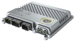
The heart of the X90 mobile system is a controller with a powerful ARM processor and up to 48 multifunction I/O channels. Basic features include connections for CAN, USB, Ethernet and the real-time POWERLINK bus system.

The extremely robust die-cast aluminum housing provides space for up to 4 additional expansion boards. These make it possible to add I/O channels or interfaces as well as specific functions such as condition monitoring.

The X90 mobile "Safety" variant is also equipped with a safe control system – also known as an X90 SafeLOGIC controller. All 48 multifunction I/Os included as standard can be used by both the standard variant and the X90 SafeLOGIC controller. Input and output signals can thus be read or operated by the standard variant and/or by the safe control system, depending on the wiring. The control lines required for this are linked by a logical AND in a safety-related manner, i.e. an output signal is only enabled if permitted by both the safety application and the standard application.

Optional Accessories
Analog inputs
X90AISG0.02-00 X90 mobile option board, strain gauge module for 2 DMS full-bridge strain gauges, 24-bit converter resolution, 5 kHz input filter
Analog outputs
X90AO410.04-00 X90 mobile option board AO, 4 analog outputs, 12-bit, optional 0 to 10 V / 0 to 20 mA, optional DI, 9 to 32 VDC, sink/source, configuration using software
X90AO410.08-00 X90 mobile option board AO, 8 analog outputs, 12-bit, optional 0 to 10 V / 0 to 20 mA, optional DI, 9 to 32 VDC, sink/source, configuration using software
BreakOut Box
X90AC-BB.17-00 X90 mobile 170, breakout box for development and tests
CMC connector
X90TB100.03-00 X90 mobile 170, connector set for CMC header, with connector contacts and dummy plugs
Communication modules
X90DSI00.04-00 X90 IO-Link option board, digital signal module, 4x IO-Link master, 4 digital channels configurable as inputs or outputs, 3-wire connections
X90IF720.04-00 X90 mobile IF option board, 3x CAN, 1x RS232 configuration using software
X90IF730.04-00 X90 mobile IF option board, 3x CAN, 1x RS485, configuration using software
X90IF7L0.05-00 X90 mobile IF option board, 3x CAN, 2x LIN (master), configuration using software
Condition Monitoring
X90CM480.04-00 X90 mobile condition monitoring, option board for vibration measurement and vibration analysis of condition monitoring tasks, 4 IEPE analog inputs
Digital inputs
X90DI110.10-00 X90 mobile option board DI, 10 digital inputs, 9 to 32 VDC, optional sink/source, optional counter input 50 kHz or AB encoder, configuration using software
Digital outputs
X90PO210.08-00 X90 mobile option board PWM, 8x PWM outputs, 9 to 32 VDC, max. 4 A, with current measurement (12-bit), 15 Hz to 1 kHz, optional DI, 9 to 32 VDC, sink/source, configuration using software
X90RO440.05-00 X90 mobile option board relay, 5 relays, normally open contact, for external actuator power supply, 9 to 32 VDC / 2 A
Motor modules
X90SM546.02-01 X90 stepper motor module, with current reduction function, module power supply 15 to 32 VDC, 2 motor connections,4 A continuous current, 8 A peak current, NetTime function
Safe digital outputs
X90RO440.04-S1 X90 mobile option board with safe relay outputs, 4 relays, normally open contacts, for external actuator power supply, 9 to 32 VDC / 2 and 4 A
Temperature measurement
X90AT910.04-00 X90 mobile option board AT, 4 resistance measurement inputs, Pt1000, optional DI, 9 to 32 VDC, sink/source, optional AI, 0 to 10 V / 0 to 32 V, 0 to 20 mA, optional PWM output, 9 to 32 VDC, 10 mA, 1 kHz, configuration using software
X90AT910.08-00 X90 mobile option board AT, 8 resistance measurement inputs, Pt1000, optional DI, 9 to 32 VDC, sink/source, optional AI, 0 to 10 V / 0 to 32 V, 0 to 20 mA, optional PWM output, 9 to 32 VDC, 10 mA, 1 kHz, configuration using software
Wire harness
X90CA100.02-00 X90 mobile 170, wiring harness starter set for X90CP17x, 2 m, for CMC header
Automation Studio HW Upgrades Version (Date) Download
V4.7 HW Upgrade (X90CP174.48-S1) EXE / 6 MB
V4.7 HW Upgrade (X90SL104.48-S1) EXE / 3 MB
V4.9 HW Upgrade (X90CP174.48-S1) EXE / 6 MB
V6.0 HW Upgrade (X90CP174.48-S1) EXE / 6 MB
Certificates Version (Date) Download
EU Declaration FS mobile automation X90 PDF / 177 KB
EU Declaration Industrial sector X90 PDF / 163 KB
EU Declaration Mobile machinery X90 PDF / 146 KB
FS Certificate X90 mobile PDF / 729 KB
FS Certificate mapp Safety PDF / 974 KB
ISOBUS Certification X90 - Test Report PDF / 181 KB
UK Declaration Industrial sector X90 PDF / 110 KB
UN ECE-R10 PDF / 382 KB
Documentation Version (Date) Download
Datasheet X90CP174.48-S1 PDF / 8 MB
X90 mobile System User´s Manual PDF / 45 MB
X90 pin allocation CMC connector ZIP / 3 MB
E-CAD (Electro or EPLAN Templates) Version (Date) Download
Makro-/Artikeldaten 4.0.2 (X90CP174.48-S1) EXE / 12 MB
X90 EPLAN P8 from V2.4 EXE / 69 MB
M-CAD (Mechan. Templates) Version (Date) Download
3D File STEP, DXF X90CP174.xx-00 ZIP / 12 MB
Tools / Utilities / Examples Version (Date) Download
Sistema library ZIP / 336 KB

Please choose country and language

B&R Logo