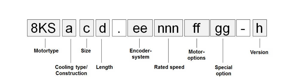
Cooling types
Cooling types C and D
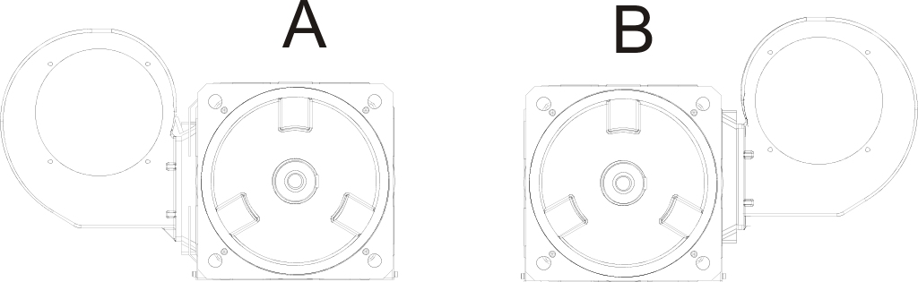
8KS three-phase synchronous motors with cooling types C and D are externally cooled using a centrifugal fan. Two different mounting directions can be ordered (position A to the left and position B to the right). Cooling type C permits flange mounting and base mounting on a B-type base. Cooling type D permits flange mounting and base mounting on the A and B side.
 |
Cooling type J
8KS three-phase synchronous motors with cooling type J are externally cooled using a highly efficient water cooling system. Size 8KSJ9 has two independent cooling circuits. The connection direction for size 8 8KSJ motors is always to the right. Size 9 8KSJ motors must always be connected on both sides. 8KSJ permits flange mounting and base mounting on a B-type base. The foot mounting on the A-side is not possible with this cooling type for mechanical reasons!
Cooling types L and M
8KS three-phase synchronous motors with cooling types L and M are externally cooled using an axial fan. Cooling type L permits flange mounting and base mounting on a B-type base. Cooling type M permits flange mounting and base mounting on the A and B side.
Size (c)
Size (c)
8KS motors are available in various sizes (8 or 8 and 9) depending on their construction. These different sizes are indicated by a number represented by (c) in the model number. The larger the number, the larger the flange dimensions and power rating for the respective motor.
Cooling type | Available sizes | |
|---|---|---|
8 | 9 | |
C | Yes | Yes |
D | Yes | -- |
J | Yes | Yes |
L | Yes | Yes |
M | Yes | --- |
Length (d)
Length (d)
8KS three-phase synchronous motors are available in four different lengths. These different lengths are indicated by a number represented by (d) in the model number.
Length | Available sizes | |
|---|---|---|
8 | 9 | |
2 | Yes | Yes |
4 | Yes | Yes |
5 | Yes | Yes |
6 | Yes | Yes |
Encoder system (ee)
Encoder system (ee)
Resolver
LTN resolvers are used in 8KS servo motors.
Name | Order code (ee) |
|---|---|
R0 | |
Accuracy | ± 6 angular minutes |
Vibration during operation | ≤ 500 m/s² |
Shock during operation | ≤ 1000 m/s² |
The shock values for the motor must be observed at all times!
EnDat 2.1 encoder
EnDat is a standard developed by Johannes Heidenhain GmbH that incorporates the advantages of absolute and incremental position measurement while also offering a read/write parameter memory in the encoder. With absolute position measurement (the absolute position is sampled serially), a homing procedure for referencing is usually not required. Where necessary, a multi-turn encoder should be installed. To reduce costs, a single-turn encoder and a reference switch can also be used. In this case, a homing procedure must be carried out. The incremental process allows the short deceleration periods necessary for position measurement when using drives with highly dynamic characteristics. With the sinusoidal incremental signal and the fine resolution in the EnDat module, a very high positioning resolution is achieved in spite of the moderate signal frequencies used.
Different types of EnDat 2.1 encoders can be used depending on requirements:
Name | Order code (ee) | |
|---|---|---|
E6 | E7 | |
Encoder type | EnDat single-turn | EnDat multi-turn |
Operating principle | Optical | Optical |
EnDat protocol | EnDat 2.1 | EnDat 2.1 |
Resolution | 2048-line | 2048-line |
Recognizable | --- | 4096 |
Number of lines | 2048 | 2048 |
Accuracy | ±20" | ±20" |
Cutoff frequency | ≥400 kHz (-3 dB) | ≥400 kHz (-3 dB) |
Vibration during operation | ≤ 300 m/s² | ≤ 300 m/s² |
Shock during operation | ≤ 2000 m/s² | ≤ 2000 m/s² |
Manufacturer's product ID | ECN 1313 EnDat01 | EQN 1325 EnDat01 |
EnDat 2.2 encoder – Safety-related position measurement systems
In machine and system manufacturing, the topic of safety is becoming more and more important. This is mirrored in legislation and stricter safety criteria in national and international standards. Most importantly, stricter requirements serve to protect personnel, but they also increasingly serve to protect property and the environment. The goal of functional safety is to minimize or eliminate dangerous situations that can occur in machines and systems either with or without operational errors. This is generally achieved by implementing redundant systems. Moving axes in safety-oriented applications require position information in order to be able to carry out their corresponding safety functions. Different system configurations can be implemented to get independent position values. One possibility is using two measuring instruments per axis. To keep costs down, the aim is often to create a solution with only one position measuring instrument. Until now, analog measuring instruments with sine/cosine signals were used for this purpose. The encoder manufacturer Heidenhain – as the first manufacturer with the purely serial EnDat 2.2 protocol for safety position measurement systems – offers a serial single-encoder solution in accordance with IEC 61 508 SIL2. All the advantages of serial data transfer – such as cost optimization, diagnostics possibilities, automatic commissioning and high-speed generation of position values – can now benefit safety applications as well.
100% inspection during production and additional measures during final testing ensure errors have not occurred related to shaft and coupling connections on rotary encoders when using motors with S encoders (in accordance with EN ISO 13849-2).
There are also a number of safety functions that are already possible with D encoders.
For information about the area of application and procedure for setting up the various safety functions, please refer to the SafeMOTION user's manual (MAACPMSAFEMC-ENG) in the Downloads section of the B&R website www.br-automation.com.
Technical data
EnDat 2.2 encoders can be used for functional safety in single-turn or multi-turn form, depending on requirements.
Name | Order code (ee) | |
|---|---|---|
S0 | S1 | |
Encoder type | EnDat single-turn functional safety | EnDat multi-turn functional safety |
Operating principle | Optical | Optical |
EnDat protocol | EnDat 2.2 | EnDat 2.2 |
Position values per revolution | 33 554 432 (25-bit) | 33 554 432 (25-bit) |
Distinguishable revolutions | --- | 4096 |
Precision | ±20" | ±20" |
Vibration during operation 10 to 2000 Hz | ≤300 m/s2 (IEC 60068-2-6) | ≤300 m/s2 (IEC 60068-2-6) |
Shock during operation Duration 6 ms | ≤2000 m/s2 (IEC 60068-2-27) | ≤2000 m/s2 (IEC 60068-2-27) |
Manufacturer's product ID | ECN 1325 FS EnDat22 | EQN1337 FS EnDat22 |
Rated speed (nnn)
Rated speed (nnn)
8KS three-phase synchronous motors can be delivered with different nominal speeds depending on the size and length.
Motor size and length | Available nominal speeds nN [rpm] | ||||||
|---|---|---|---|---|---|---|---|
1000 | 1100 | 1500 | 1600 | 2000 | 2500 | 3000 | |
8KSC8 | -- | Yes | -- | Yes | Yes | Yes | Yes |
8KSD8 | -- | Yes | -- | Yes | Yes | Yes | Yes |
8KSL8 | -- | Yes | Yes | Yes | Yes | Yes | |
8KSM8 | -- | Yes | -- | Yes | Yes | Yes | Yes |
8KSC92,94 | Yes | -- | Yes | -- | Yes | Yes | Yes |
8KSC95 | Yes | -- | Yes | -- | Yes | Yes | -- |
8KSC96 | Yes | -- | Yes | -- | Yes | -- | -- |
8KSL92,94 | Yes | -- | Yes | -- | Yes | Yes | Yes |
8KSL95 | Yes | -- | Yes | -- | Yes | Yes | -- |
8KSL96 | Yes | -- | Yes | -- | Yes | -- | -- |
Motor size and length | Available nominal speeds nN [rpm] | ||||
|---|---|---|---|---|---|
1000 | 1500 | 2000 | 2500 | 3000 | |
8KSJ82, 84, 85 | Yes | Yes | Yes | Yes | Yes |
8KSJ86 | Yes | Yes | Yes | Yes | -- |
8KSJ92 | Yes | Yes | Yes | Yes | -- |
8KSJ94 | Yes | Yes | Yes | -- | -- |
8KSJ95 | Yes | Yes | -- | -- | -- |
8KSJ96 | Yes | -- | -- | -- | -- |
Connection direction
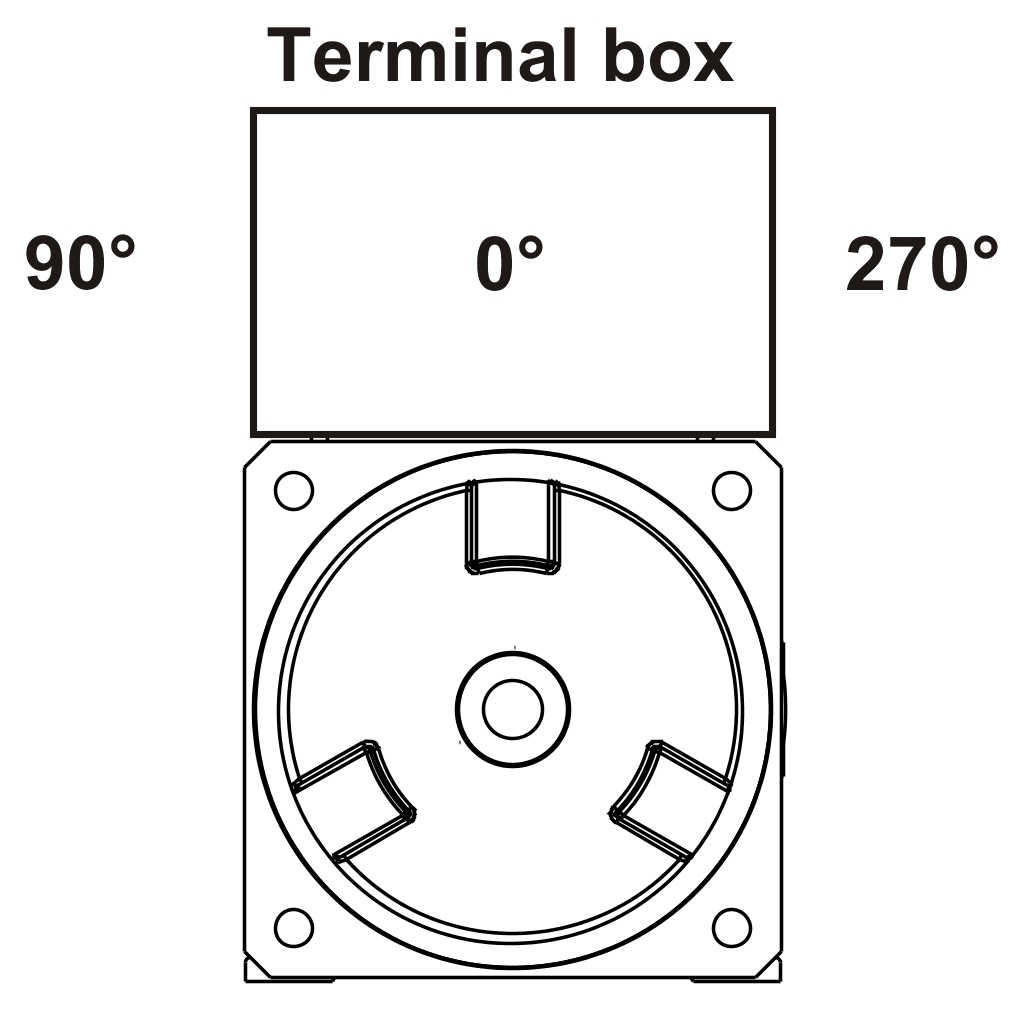
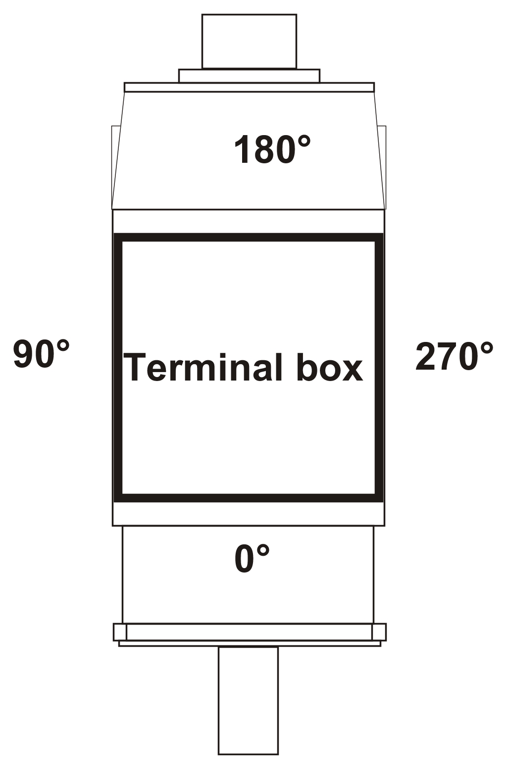
Connection direction
The power connection for 8KS three-phase synchronous motors is generally made using terminal boxes. The position of the terminal box is "top" and the cable outlet is "right" (corresponds to 270°).
 |  |
Motor version (h)
Motor version (h)
The motor version is automatically specified by the configurator and can be seen in the technical data.
Determining the order code for motor options (ff)
The respective code (ff) for the order key can be found in the following table:
Motor options for cooling types C, D and J (centrifugal fans and water cooling)
Motor option | |||||
|---|---|---|---|---|---|
Connectiondirection | Oil seal | Holding brake | Shaft end | Mounting direction / connection direction Cooling unit | Code for the order key (ff) |
Terminal box on the top, cable outlet is 270° (right) | No | No | Smooth | Fan on the left | A0 |
Keyed | Fan on the left | A1 | |||
Normal | Smooth | Fan on the left | A2 | ||
Keyed | Fan on the left | A3 | |||
No | Smooth | Fan/Water lines on the right | B0 | ||
Keyed | Fan/Water lines on the right | B1 | |||
Normal | Smooth | Fan/Water lines on the right | B2 | ||
Keyed | Fan/Water lines on the right | B3 | |||
NOTE: For 8KSJ motors, it is onlypossible to select "B" options since the water lines on the 8KSJ8 are always located on the right side. For size 8KSJ9, it must always be connected on both sides since two cooling circuits must be supplied.
Motor options for cooling types L and M (axial fans)
Motor option | |||||
|---|---|---|---|---|---|
Connection direction | Oil seal | Holding brake | Shaft end | Mounting direction / connection direction for the cooling unit | Code for the order key (ff) |
Terminal box on the top, cable outlet is 270° (right) | No | No | Smooth | Axial | C0 |
Keyed | Axial | C1 | |||
Normal | Smooth | Axial | C2 | ||
Keyed | Axial | C3 | |||
8KS mounting types
Mounting type | Flange and B-foot | Flange, A- and B-foot | ||||
|---|---|---|---|---|---|---|
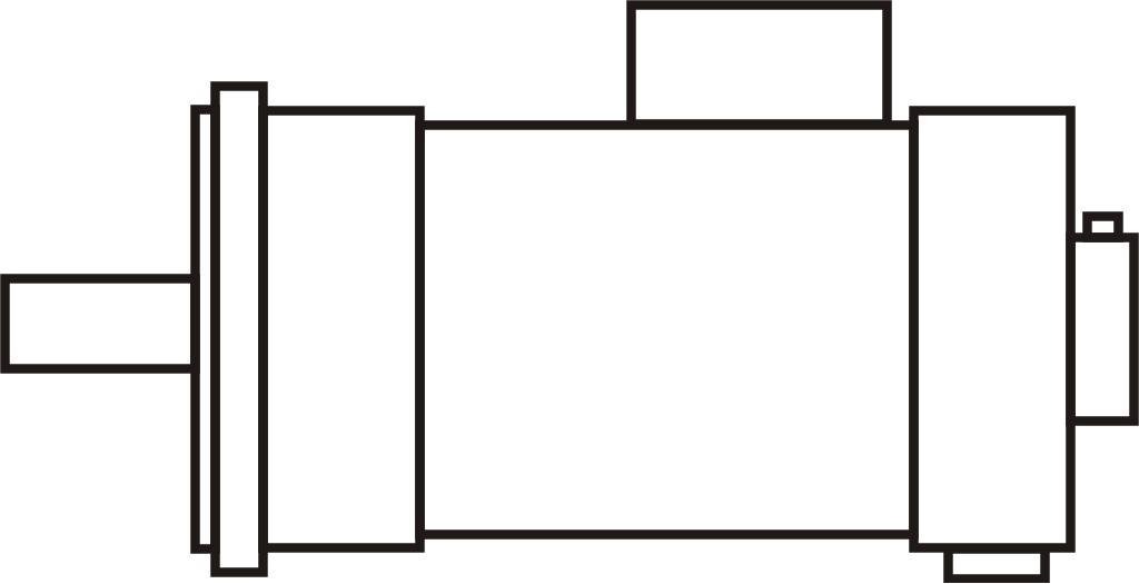 | 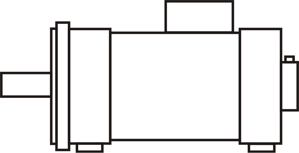 | |||||
8KSC | Yes | --- | ||||
8KSD | --- | Yes | ||||
8KSJ | Yes | --- | ||||
8KSL | Yes | --- | ||||
8KSM | --- | Yes | ||||
Special motor options (gg)
The respective code (gg) for the order key can be found in the following table.
Special option | Order code |
|---|---|
No special option | 00 |
Reinforced bearings | 04 |
Square filter for centrifugal fans (cooling type C and D) | 15 |
ExampleOrder 1
ExampleOrder 1
A fan-cooled 8KS three-phase synchronous motor with size84 is selected for the application. The motor should be equipped with a mounting base on the A side in addition to the existing mounting base on the B side. The name is therefore 8KSD. A single-turn encoder with functional safety was chosen. The required speed is 2500 rpm. The radially-mounted fan should be on the left side of the motor. A brake is not required, the output shaft should be smooth. The fan should be equipped with a filter that is available as a special option.
The code (ee) for the encoder system is S0.
The code (nnn) for a nominal speed of 2500 rpm is 025.
The option code (ff) for fan-cooled 8KS motors with the fan on the left side is always "A". All 8KS motors are equipped with a terminal box (position on the top and cable channel outlet on the right, that corresponds to 270°). The no holding brake and smooth shaft options result in "0", so the option code is "A0"
The special option code (gg) for the filter (square filter) is 15.
The model number for the required motor is 8KSD84.S0025A015-0
ExampleOrder 2
ExampleOrder 2
A water-cooled 8KSJ three-phase synchronous motor with size92 is selected for the application. A multi-turn encoder with functional safety was chosen. The required speed is 2000 rpm. A brake is not required, the output shaft should have a keyway.
The code (ee) for the encoder system is S1.
The code (nnn) for a nominal speed of 2000 rpm is 020.
The option code (ff) for water-cooled 8KSJ motors is always "B". All 8KS motors are equipped with a terminal box (position on the top and cable channel outlet on the right, that corresponds to 270°). The no holding brake and shaft key options result in "1", so the option code is "B1"
No special options.
The model number for the required motor is 8KSJ92.S1020B100-0