General information
| Certifications | |
| CE | Yes |
| UKCA | Yes |
| CRA (Cyber Resilience Act) | Non-compliant |
| Functional safety | Yes |
| UL |
cULus E225616 Power conversion equipment |
| KC | Yes |
| Note | Variant with partially coated printed circuit boards |
| B&R ID code | 0xA099 |
| Slots for plug-in modules | 4 |
Mains connection
DC bus connection
| DC bus capacitance | 235 µF |
24 VDC power supply
Motor connection
Motor holding brake connection
| Response threshold for open-circuit monitoring | Approx. 385 mA |
| Max. output current | 1 A |
| Max. number of switching cycles | Unlimited since implemented electronically |
Braking resistor
| Peak power output | 3.5 kW |
| Continuous power | 130 W |
Limit switch and reference inputs
| Electrical isolation | |
| Input - ACOPOS | Yes |
| Input - Input | No |
| Input voltage | |
| Nominal | 24 VDC |
| Maximum | 30 VDC |
| Switching threshold | |
| Low | <5 V |
| High | >15 V |
| Quantity | 3 |
| Circuit | Sink |
| Input current at nominal voltage | Approx. 4 mA |
| Switching delay | Max. 2.0 ms |
| Modulation compared to ground potential | Max. ±38 V |
Enable inputs
Trigger inputs
| Electrical isolation | |
| Input - ACOPOS | Yes |
| Input - Input | No |
| Input voltage | |
| Nominal | 24 VDC |
| Maximum | 30 VDC |
| Switching threshold | |
| Low | <5 V |
| High | >15 V |
| Switching delay | |
| Rising edge | 52 µs ±0.5 µs (digitally filtered) |
| Falling edge | 53 µs ±0.5 µs (digitally filtered) |
| Quantity | 2 |
| Circuit | Sink |
| Input current at nominal voltage | Approx. 10 mA |
| Modulation compared to ground potential | Max. ±38 V |
Electrical properties
Operating conditions
Ambient conditions
Mechanical properties
| Dimensions | |
| Width | 70.5 mm |
| Height | 375 mm |
| Depth | 235.5 mm |
| Weight | 4.0 kg |
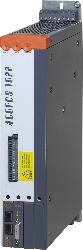
Référence produit:
8V1022.001-2Description:
- Modular mechanical design using plug-in modules
- Integrated line filter
- Integrated braking resistor
- All connections are made using plug-in connectors
- Integrated electronic restart inhibit
- Partially-coated circuit boards - more robust in regard to environmental influences (8Vxxxx.001-2)
Inclus dans la livraison
Shield component sets
| 8X0010.00-1 | ACOPOS shield component set for 8V1022.xxx-x to 8V1090.xxx-x |
Terminal block sets
| 8X0001.00-1 | ACOPOS accessories, connector set for 8V1010.00 to 8V1090.00 (3-phase) |
Accessoires optionnels
Plug-in modules
| 8AC131.60-1 | ACOPOS plug-in module, 2 analog inputs ±10 V, 2 digital I/Os configurable as 24 V input or output 45 mA, order terminal block TB712 separately! |
| 8AC130.60-1 | ACOPOS plug-in module, 8 digital I/O configurable in pairs as 24 V inputs or outputs 400/100 mA, 2 digital outputs 2 A, order terminal block TB712 separately! |
| 8AC126.60-1 | ACOPOS plug-in module, EnDat 2.2 encoder interface |
| 8AC125.61-2 | ACOPOS plug-in module, BiSS encoder interface 12 V, baud rate 6.25 Mbit/s |
| 8AC125.60-2 | ACOPOS plug-in module, BiSS encoder interface 5 V, baud rate 6.25 Mbit/s |
| 8AC125.60-1 | ACOPOS plug-in module, BiSS/SSI SinCos/SSI interface |
| 8AC123.60-1 | ACOPOS plug-in module, incremental encoder and SSI absolute encoder interface |
| 8AC122.60-3 | ACOPOS plug-in module, resolver interface 10 kHz |
| 8AC121.60-1 | ACOPOS plug-in module, HIPERFACE interface |
| 8AC120.60-1 | ACOPOS plug-in module, EnDat encoder and sine incremental encoder interface |
| 8AC114.60-2 | ACOPOS plug-in module, POWERLINK V2 interface |
| 8AC110.60-3 | ACOPOS plug-in module, CAN interface |
| Automation Studio HW Upgrades | Version (date) | Téléchargement |
|---|---|---|
| V4.0 HW Upgrade (8V1022.001-2) | EXE / 214 Ko | |
| V6.0 HW Upgrade (8V1022.001-2) | EXE / 287 Ko |
| Documentation | Version (date) | Téléchargement |
|---|---|---|
| ACOPOS User´s Manual | PDF / 49 Mo | |
| Datasheet 8V1022.001-2 | PDF / 2 Mo | |
| Safety Guidelines | PDF / 1 Mo |
| E-CAD (modèles Electro ou EPLAN) | Version (date) | Téléchargement |
|---|---|---|
| ACOPOS EPLAN P8 from V2.4 | EXE / 23 Mo |
| M-CAD (modèles mécaniques) | Version (date) | Téléchargement |
|---|---|---|
| 3D file STEP ACOPOS 1022/1045/1090 | ZIP / 2 Mo |
| Outils / Utilitaires / Exemples | Version (date) | Téléchargement |
|---|---|---|
| Sistema (VDMA) library | ZIP / 6 Ko |