Short description
| Bus controller | POWERLINK (V1/V2) controlled node |
General information
| B&R ID code | |
| Bus controller | 0xED84 |
| Diagnostics | |
| Outputs | Yes, using LED status indicator and software |
| Power supply | Yes, using LED status indicator and software |
| Support | |
| Dynamic node allocation (DNA) | Yes |
| Connection type | |
| Fieldbus | M12, D-coded |
| Inputs/Outputs | 8x M12, A-coded |
| I/O power supply | M8, 4-pin |
| Power consumption | |
| Internal I/O | 2.5 W |
| Certifications | |
| CE | Yes |
| UKCA | Yes |
| CRA (Cyber Resilience Act) | In preparation |
| Inputs/Outputs | 8 CAN interfaces |
| Insulation voltage between channel and bus | 500 Veff |
| Nominal voltage | 24 VDC |
| Status indicators | TX/RX per CAN interface, supply voltage, bus function |
Fieldbus
Interfaces
Sensor/Actuator power supply
| Voltage | 9 to 32 V |
| Voltage drop for short-circuit protection at 0.5 A | Max. 2 VDC |
| Summation current | Max. 1.6 A (200 mA per channel) |
| Short-circuit proof | Yes |
Power supply
| Nominal voltage | 24 VDC |
| Voltage range | 9 to 32 VDC |
| Reverse polarity protection | Yes |
Electrical properties
| Electrical isolation |
POWERLINK isolated from channel Channel not isolated from channel |
Operating conditions
| Mounting orientation | |
| Any | Yes |
| Installation elevation above sea level | |
| 0 to 2000 m | No limitation |
| >2000 m | Reduction of ambient temperature by 0.5°C per 100 m |
| Degree of protection per EN 60529 | IP67 |
Ambient conditions
| Temperature | |
| Operation | -25 to 60°C |
| Derating | - |
| Storage | -40 to 85°C |
| Transport | -40 to 85°C |
Mechanical properties
| Dimensions | |
| Width | 53 mm |
| Height | 155 mm |
| Depth | 42 mm |
| Torque for connections | |
| M8 | Max. 0.4 Nm |
| M12 | Max. 0.6 Nm |
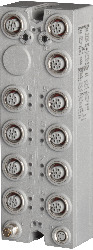
Material number:
X67BC8780.L12Description:
- POWERLINK
- 8 CAN interfaces
- M12 connections
- Integrated hub for efficient cabling
This bus controller makes it possible to connect 8 CAN interfaces to the POWERLINK network. The CAN interfaces are operated via an integrated hub, which increases the total cable length defined by classical CAN bus topology.
POWERLINK is a standard protocol for Fast Ethernet equipped with hard real-time characteristics. The Ethernet POWERLINK Standardization Group (EPSG) ensures openness and continuous development: www.ethernet-powerlink.org.
| Automation Studio HW Upgrades | Version (Date) | Download |
|---|---|---|
| V4.3 HW Upgrade (X67BC8780.L12) | EXE / 5 MB |
| Certificates | Version (Date) | Download |
|---|---|---|
| EU Declaration ATEX X67 | PDF / 191 KB | |
| EU Declaration PLC X67 | PDF / 674 KB | |
| UK Declaration PLC X67 | PDF / 469 KB |
| Documentation | Version (Date) | Download |
|---|---|---|
| Data sheet X67BC8780.L12 | PDF / 2 MB | |
| POWERLINK Bus Controller User's Manual | PDF / 3 MB | |
| X67 System User´s Manual | PDF / 19 MB |
| E-CAD (Electro or EPLAN Templates) | Version (Date) | Download |
|---|---|---|
| X67 EPLAN P8 from V2.4 | EXE / 105 MB |
| M-CAD (Mechan. Templates) | Version (Date) | Download |
|---|---|---|
| STEP File X67BC8xxx.L12 | ZIP / 1 MB |