Short description
| Bus controller | CAN I/O |
General information
| B&R ID code | |
| Bus controller | 0x18CB |
| Internal I/O module | 0x1311 |
| Diagnostics | |
| Outputs | Yes, using LED status indicator and software |
| I/O power supply | Yes, using LED status indicator and software |
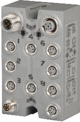
| Connection type | |
| Fieldbus | M12, A-coded |
| X2X Link | M12, B-coded |
| Inputs/Outputs | 8x M8, 3-pin |
| I/O power supply | M8, 4-pin |
| Power consumption | |
| Fieldbus | 2.1 W |
| Internal I/O | 2 W |
| X2X Link power supply | 6.2 W at maximum power output for connected I/O modules |
| Certifications | |
| CE | Yes |
| UKCA | Yes |
| CRA (Cyber Resilience Act) | In preparation |
| ATEX |
Zone 2, II 3G Ex nA IIA T5 Gc IP67, Ta = 0 - Max. 60°C TÜV 05 ATEX 7201X |
| UL |
cULus E115267 Industrial control equipment |
| HazLoc |
cCSAus 244665 Process control equipment for hazardous locations Class I, Division 2, Groups ABCD, T5 |
| KC | Yes |
| Inputs/Outputs | 8 digital channels, configurable as inputs or outputs using software, inputs with additional functions |
| Insulation voltage between channel and bus | 500 Veff |
| Nominal voltage | 24 VDC |
| Sensor/Actuator power supply | 0.5 A summation current |
| Status indicators | I/O function per channel, supply voltage, bus function |
| Power output | 3 W X2X Link power supply for I/O modules |
Interfaces
I/O power supply
Sensor/Actuator power supply
| Voltage | I/O power supply minus voltage drop for short-circuit protection |
| Voltage drop for short-circuit protection at 0.5 A | Max. 2 VDC |
| Summation current | Max. 0.5 A |
| Short-circuit proof | Yes |
Digital inputs
| Input filter | |
| Hardware | ≤10 μs (channels 1 to 4) / ≤70 µs (channels 5 to 8) |
| Software | Default 0 ms, configurable between 0 and 25 ms in 0.2 ms intervals |
| Switching threshold | |
| Low | <5 VDC |
| High | >15 VDC |
| Input characteristics per EN 61131-2 | Type 1 |
| Input voltage | 18 to 30 VDC |
| Input current at 24 VDC | Typ. 4 mA |
| Input circuit | Sink |
| Input resistance | Typ. 6 kΩ |
| Additional functions | 50 kHz event counting, gate measurement |
Event counters
| Quantity | 2 |
| Signal form | Square wave pulse |
| Evaluation | Each negative edge, cyclic counter |
| Input frequency | Max. 50 kHz |
| Counter 1 | Input 1 |
| Counter 2 | Input 3 |
| Counter frequency | Max. 50 kHz |
| Counter size | 16-bit |
Gate time measurement
| Counter frequency | |
| Internal | 48 MHz, 3 MHz, 187.5 kHz |
| Quantity | 1 |
| Signal form | Square wave pulse |
| Evaluation | Positive edge - Negative edge |
| Counter size | 16-bit |
| Length of pause between pulses | ≥100 µs |
| Pulse length | ≥20 µs |
| Supported inputs | Input 2 or input 4 |
Digital outputs
| Switching delay | |
| 0 → 1 | <400 µs |
| 1 → 0 | <400 µs |
| Switching frequency | |
| Resistive load | Max. 100 Hz |
| Inductive load | See section "Switching inductive loads". |
| Variant | Current-sourcing FET |
| Switching voltage | I/O power supply minus residual voltage |
| Nominal output current | 0.5 A |
| Total nominal current | 4 A |
| Output circuit | Source |
| Output protection | Thermal shutdown in the event of overcurrent or short circuit, integrated protection for switching inductive loads, reverse polarity protection of the output power supply |
| Diagnostic status | Output monitoring with 10 ms delay |
| Leakage current when the output is switched off | 5 µA |
| Switching on after overload shutdown | Approx. 10 ms (depends on the module temperature) |
| Residual voltage | <0.3 V at 0.5 A nominal current |
| Peak short-circuit current | <12 A |
| Braking voltage when switching off inductive loads | 50 VDC |
Electrical properties
| Electrical isolation |
Channel isolated from CAN I/O and bus CAN I/O not isolated from bus and channel not isolated from channel |
Operating conditions
| Mounting orientation | |
| Any | Yes |
| Installation elevation above sea level | |
| 0 to 2000 m | No limitation |
| >2000 m | Reduction of ambient temperature by 0.5°C per 100 m |
| Degree of protection per EN 60529 | IP67 |
Ambient conditions
| Temperature | |
| Operation | -25 to 60°C |
| Derating | - |
| Storage | -40 to 85°C |
| Transport | -40 to 85°C |
Mechanical properties
| Dimensions | |
| Width | 53 mm |
| Height | 85 mm |
| Depth | 42 mm |
| Torque for connections | |
| M8 | Max. 0.4 Nm |
| M12 | Max. 0.6 Nm |
| Weight | 195 g |
Material number:
X67BC7321-1Description:
- Fieldbus: CAN bus
- 8 digital channels, configurable as inputs or outputs
- Integrated I/O access in B&R Automation Studio
- Automatic firmware update via the fieldbus
- X67 connection possibility for all B&R CPUs
The bus controller makes it possible to connect X2X Link I/O nodes to CAN I/O. CAN I/O is a transfer protocol based on standard CAN bus that is fully integrated in the B&R system.
Up to 43 logic I/O modules can be connected to the bus controller. Up to 16 of them can be analog modules.
With multifunction modules, the bus controller supports only the default function model in the event of automatic configuration by the bus controller (see the respective module description).
| Automation Studio HW Upgrades | Version (Date) | Download |
|---|---|---|
| AS 2.6 HW Upgrade (X67BC7321-1a) | EXE / 539 KB | |
| AS 3.0 HW Upgrade (X67BC7321-1a) | EXE / 539 KB | |
| V2.6 HW Upgrade (X67BC7321-1) | EXE / 2 MB | |
| V3.0 HW Upgrade (X67BC7321-1) | EXE / 3 MB | |
| V4.0 HW Upgrade (X67BC7321-1) | EXE / 2 MB |
| Documentation | Version (Date) | Download |
|---|---|---|
| Datasheet X67BC7321-1 | PDF / 2 MB | |
| X67 System User´s Manual | PDF / 19 MB |
| E-CAD (Electro or EPLAN Templates) | Version (Date) | Download |
|---|---|---|
| X67 EPLAN P8 from V2.4 | EXE / 105 MB |
| M-CAD (Mechan. Templates) | Version (Date) | Download |
|---|---|---|
| 3D File DXF/STEP X67 | ZIP / 1 MB |