Short description
| I/O module | 2x 2 safe analog inputs for thermocouples, 1x 2 safe analog inputs for PT100/PT1000 sensors, channel pairs galvanically isolated, integrated terminal temperature compensation, integrated temperature sensor in terminal block X20TB5E |
General information
| B&R ID code | 0xB419 |
| Status indicators | I/O function per channel, operating state, module status |
| Diagnostics | |
| Module run/error | Yes, using LED status indicator and software |
| Inputs | Yes, using LED status indicator and software |
| Blackout mode | |
| Scope | Module |
| Function | Module functionality |
| Standalone mode | No |
| Power consumption | |
| Bus | 0.25 W |
| Internal I/O | 1.2 W |
| Additional power dissipation caused by actuators (resistive) [W] | - |
| Electrical isolation | |
| Channel - Bus | Yes |
| Channel - Channel | No |
| Channel pair - Channel pair | Yes |
| Certifications | |
| CE | Yes |
| UKCA | Yes |
| CRA (Cyber Resilience Act) | In preparation |
| Functional safety |
cULus FSPC E361559 Energy and industrial systems Certified for functional safety ANSI UL 1998:2013 |
| Functional safety |
IEC 61508:2010, SIL 3 EN 62061:2005/A2:2015, SIL 3 EN ISO 13849-1:2015, Cat. 4 / PL e IEC 61511:2004, SIL 3 |
| Functional safety | EN 50156-1:2004 |
| ATEX |
Zone 2, II 3G Ex nA nC IIA T5 Gc IP20, Ta (see X20 user's manual) FTZÚ 09 ATEX 0083X |
| UL |
cULus E115267 Industrial control equipment cULus E537419 Engine generator controller |
| HazLoc |
cCSAus 244665 Process control equipment for hazardous locations Class I, Division 2, Groups ABCD, T5 |
| DNV |
Temperature: A (0 to 45°C) Humidity: B (up to 100%) Vibration: A (0.7 g) EMC: B (bridge and open deck) |
| CCS | Yes |
| LR | ENV1 |
| KR | Yes |
| ABS | Yes |
| BV |
EC21B Temperature: 5 - 45°C Vibration: 0.7 g EMC: Bridge and open deck |
| KC | Yes |
Safety characteristics
| Note | See section "Safety characteristics". |
I/O power supply
| Nominal voltage | 24 VDC |
| Voltage range | 24 VDC -15% / +20% |
Thermocouple temperature inputs
Resistance measurement temperature inputs
Operating conditions
| Mounting orientation | |
| Horizontal | Yes |
| Vertical | Yes |
| Installation elevation above sea level | 0 to 2000 m, no limitation |
| Degree of protection per EN 60529 | IP20 |
Ambient conditions
| Temperature | |
| Operation | |
| Horizontal mounting orientation | 0 to 60°C |
| Vertical mounting orientation | 0 to 50°C |
| Derating | See section "Derating". |
| Storage | -40 to 85°C |
| Transport | -40 to 85°C |
| Relative humidity | |
| Operation | 5 to 95%, non-condensing |
| Storage | 5 to 95%, non-condensing |
| Transport | 5 to 95%, non-condensing |
Mechanical properties
| Note |
Order 1x safety-keyed terminal block separately. Order 1x safety-keyed bus module separately. |
| Pitch | 25+0.2 mm |
Material number:
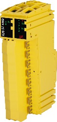
X20ST4492Description:
- 2 safe analog input pairs for thermocouples
- For sensor types J, K, N, S, R, C, T, raw value measurement
- 1 safe analog input pair for resistance temperature measurement
- For PT100 and PT1000
- Configurable sensor type per channel
- 24-bit digital converter resolution
- Galvanically isolated analog channel pairs
- Input filter configurable
- Integrated terminal temperature compensation
- 2x PT1000 sensor integrated in the terminal (X20TB5E)
- 2x external PT1000 sensor can be connected (X20TB5F)
The module is equipped with 2 safe analog input pairs for J, K, N, S, R, C and T thermocouple sensors and 1 safe analog input pair for PT100/PT1000 resistance temperature measurement.
The safe temperature module is suitable for safely acquiring temperatures for safety-related applications up to PL e or SIL 3.
This module is designed for X20 16-pin terminal blocks.
Mandatory Accessories
Bus modules
| Automation Studio HW Upgrades | Version (Date) | Download |
|---|---|---|
| V3.0 HW Upgrade (X20ST4492) | EXE / 2 MB | |
| V4.0 HW Upgrade (X20ST4492) | EXE / 2 MB | |
| V4.6 HW Upgrade (X20ST4492) | EXE / 944 KB | |
| V6.0 HW Upgrade (X20ST4492) | EXE / 826 KB |
| Documentation | Version (Date) | Download |
|---|---|---|
| Data sheets SafeIO and SafeLogic | PDF / 29 MB | |
| Integrated safety technology user's manual | PDF / 59 MB | |
| X20 Package leaflet ATEX/CSA | PDF / 2 MB | |
| X20 System User´s Manual | PDF / 49 MB |
| E-CAD (Electro or EPLAN Templates) | Version (Date) | Download |
|---|---|---|
| X20 EPLAN P8 from V2.4 | EXE / 160 MB |
| M-CAD (Mechan. Templates) | Version (Date) | Download |
|---|---|---|
| 3D file STEP X20(c)Sxxxxx - Terminal block right side | ZIP / 21 KB | |
| DFX File I/O Slice | ZIP / 4 KB | |
| Dimensions PDF X20 I/O Slice | PDF / 45 KB |
| Tools / Utilities / Examples | Version (Date) | Download |
|---|---|---|
| Sistema (VDMA) library | ZIP / 5 KB |