Short description
| Bus receiver | X2X Link bus receiver with supply for I/O and bus |
General information
X2X Link power supply input
| Input voltage | 24 VDC -15% / +20% |
| Input current | Max. 0.7 A |
| Fuse | Integrated, cannot be replaced |
| Reverse polarity protection | Yes |
X2X Link power supply output
Input I/O power supply
| Input voltage | 24 VDC -15% / +20% |
| Fuse | Required line fuse: Max. 10 A, slow-blow |
| Reverse polarity protection | No |
Output I/O power supply
| Nominal output voltage | 24 VDC |
| Behavior on short circuit | Required line fuse |
| Permissible contact load | 10 A |
Electrical properties
| Electrical isolation |
X2X Link supply isolated from X2X Link power supply I/O supply not isolated from I/O power supply
|
Operating conditions
| Mounting orientation | |
| Horizontal | Yes |
| Vertical | Yes |
| Installation elevation above sea level | |
| 0 to 2000 m | No limitation |
| >2000 m | Reduction of ambient temperature by 0.5°C per 100 m |
| Degree of protection per EN 60529 | IP20 |
Ambient conditions
| Temperature | |
| Operation | |
| Horizontal mounting orientation | -25 to 60°C |
| Vertical mounting orientation | -25 to 50°C |
| Derating | See section "Derating". |
| Starting temperature | Yes, -40°C |
| Storage | -40 to 85°C |
| Transport | -40 to 85°C |
| Relative humidity | |
| Operation | Up to 100%, condensing |
| Storage | 5 to 95%, non-condensing |
| Transport | 5 to 95%, non-condensing |
Mechanical properties
| Note |
Order 1x terminal block X20TB12 separately. Order 1x power supply bus module X20cBM01 separately |
| Pitch | 12.5+0.2 mm |
型番:
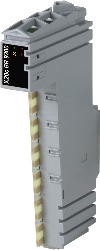
X20cBR9300説明:
- X2X Link bus receiver
- Feed for X2X Link and internal I/O supply
- Electrical isolation of feed and X2X Link supply
- Redundancy of X2X Link supply possible by operating multiple supply modules simultaneously
- Operation only on the slot to the far left
The bus receiver is used to connect the X20 System to the X2X Link. The module is equipped with a feed for the X2X Link as well as the internal I/O supply.
必須アクセサリ
Bus modules
| X20cBM01 | X20 power supply bus module, coated, 24 VDC keyed, internal I/O power supply interrupted to the left |
Terminal blocks
| X20TB12 | X20 terminal block, 12-pin, 24 VDC keyed |
オプションで付属可
X2X Link Cable
| X67CA0X99.1000 | Cable for custom assembly, 100 m |
| X67CA0X99.5000 | Cable for custom assembly, 500 m |
| Automation Studio HW アップグレード | バージョン (日付) | ダウンロード |
|---|---|---|
| V3.0 HW Upgrade (X20cBR9300) | EXE / 1 MB | |
| V4.0 HW Upgrade (X20cBR9300) | EXE / 914 KB | |
| V6.0 HW Upgrade (X20cBR9300) | EXE / 930 KB |
| E-CAD(ElectroまたはEPLANテンプレート) | バージョン (日付) | ダウンロード |
|---|---|---|
| X20 EPLAN P8 from V2.4 | EXE / 160 MB |
| M-CAD (Mechan.Templates) | バージョン (日付) | ダウンロード |
|---|---|---|
| 3D File DXF/STEP X20 Electronic module | ZIP / 10 KB | |
| 3D File STEP X20 I/O-Slice | ZIP / 872 KB | |
| Dimensions PDF X20 Electronic module | PDF / 3 KB |
| ドキュメンテーション | バージョン (日付) | ダウンロード |
|---|---|---|
| Coated modules | PDF / 62 KB | |
| Datasheet X20(c)BR9300 | PDF / 510 KB | |
| X20 Package leaflet ATEX/CSA | PDF / 2 MB | |
| X20 System User´s Manual | PDF / 49 MB |