Short description
| Bus controller | Modbus TCP/UDP slave |
General information
| B&R ID code | 0x227C |
| Status indicators | Module status, bus function |
| Diagnostics | |
| Module status | Yes, using LED status indicator and software |
| Bus function | Yes, using LED status indicator and software |
| Power consumption | |
| Bus | 2 W |
| Additional power dissipation caused by actuators (resistive) [W] | - |
| Certifications | |
| CE | Yes |
| UKCA | Yes |
| CRA (Cyber Resilience Act) | Evaluation ongoing |
| ATEX |
Zone 2, II 3G Ex nA nC IIA T5 Gc IP20, Ta (see X20 user's manual) FTZÚ 09 ATEX 0083X |
| UL |
cULus E115267 Industrial control equipment |
| HazLoc |
cCSAus 244665 Process control equipment for hazardous locations Class I, Division 2, Groups ABCD, T5 |
| DNV |
Temperature: B (0 to 55°C) Humidity: B (up to 100%) Vibration: B (4 g) EMC: B (bridge and open deck) |
| CCS | Yes |
| LR | ENV1 |
| KR | Yes |
| ABS | Yes |
| BV |
EC33B Temperature: 5 - 55°C Vibration: 4 g EMC: Bridge and open deck |
| KC | Yes |
Interfaces
Electrical properties
| Electrical isolation | Modbus isolated from bus and I/O |
Operating conditions
| Mounting orientation | |
| Horizontal | Yes |
| Vertical | Yes |
| Installation elevation above sea level | |
| 0 to 2000 m | No limitation |
| >2000 m | Reduction of ambient temperature by 0.5°C per 100 m |
| Degree of protection per EN 60529 | IP20 |
Ambient conditions
| Temperature | |
| Operation | |
| Horizontal mounting orientation | -25 to 60°C |
| Vertical mounting orientation | -25 to 50°C |
| Derating | - |
| Storage | -40 to 85°C |
| Transport | -40 to 85°C |
| Relative humidity | |
| Operation | 5 to 95%, non-condensing |
| Storage | 5 to 95%, non-condensing |
| Transport | 5 to 95%, non-condensing |
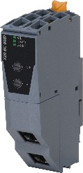
Material number:
X20BC0087Description:
- Fieldbus: Modbus/TCP, Modbus/UDP
- I/O configuration via the fieldbus
- DHCP-capable
- Bootp-capable
- Integrated double switch for efficient cabling
- Configurable I/O cycle (0.5 to 4 ms)
- Response time: <1 to 8 ms (depending on the load on the integrated switch)
- Validity check for command sequences before execution
Established in 1979, the Modbus protocol has approved the use of Ethernet with both Modbus TCP and Modbus/UDP. Today, Modbus TCP is an open Internet draft standard introduced by Schneider Automation to the Internet Engineering Task Force (IETF), the organization responsible for Internet standardization. The Modbus services and object model have been preserved since the original version and left unchanged for use with the TCP/IP transmission medium.
Modbus/UDP differs from Modbus TCP in that it uses connectionless communication via UDP/IP. The advantages of faster and easier communication with UDP/IP also brings with it the disadvantage of requiring error detection and correction in the application layer.
This bus controller makes it possible to connect X2X Link I/O nodes to Modbus via Ethernet. The bus controller can be operated on B&R controllers through the use of Automation Studio or on third-party systems with Modbus TCP or -UDP master functionality.
With multifunction modules, the bus controller supports only the default function model in the event of automatic configuration by the bus controller (see the respective module description).
All other function models are supported when configured accordingly in Automation Studio V4.3 or later.
Automation Studio kann kostenlos von der B&R Webseite www.br-automation.com heruntergeladen werden. Die Evaluierungslizenz darf unentgeltlich zur Erstellung vollständiger Konfigurationen der Feldbus Bus Controller benützt werden.
Mandatory Accessories
System modules for bus controllers
| X20BB80 | X20 bus base, for X20 base module (BC, HB, etc.) and X20 power supply module, X20 end cover plates (left and right) X20AC0SL1/X20AC0SR1 included |
| X20PS9400 | X20 power supply module, for bus controller and internal I/O power supply X2X Link power supply |
| X20PS9402 | X20 power supply module, for bus controller and internal I/O power supply, X2X Link supply, supply not galvanically isolated |
Terminal blocks
| X20TB12 | X20 terminal block, 12-pin, 24 VDC keyed |
| Automation Studio HW Upgrades | Version (Date) | Download |
|---|---|---|
| V3.0 HW Upgrade (X20BC0087) | EXE / 399 KB | |
| V4.3 HW Upgrade (X20BC0087) | EXE / 776 KB |
| Documentation | Version (Date) | Download |
|---|---|---|
| Data sheet X20(c)BC0087 | PDF / 2 MB | |
| Modbus/TCP Bus Controller User's manual | PDF / 22 MB | |
| X20 Package leaflet ATEX/CSA | PDF / 2 MB | |
| X20 System User´s Manual | PDF / 49 MB |
| E-CAD (Electro or EPLAN Templates) | Version (Date) | Download |
|---|---|---|
| X20 EPLAN P8 from V2.4 | EXE / 160 MB |
| Fieldbus equipment description files | Version (Date) | Download |
|---|---|---|
| Modbus Mapping Tool | ZIP / 480 KB | |
| ModbusTCP Toolbox | ZIP / 4 MB |
| M-CAD (Mechan. Templates) | Version (Date) | Download |
|---|---|---|
| 3D File STEP/DXF X20BC and X20IF Module | ZIP / 1 MB |