Short description
| Bus controller | CAN I/O slave |
General information
| Diagnostics | |
| Module status | Yes, using LED status indicator and software |
| Bus function | Yes, using LED status indicator |
| Data transfer | Yes, using LED status indicator |
| Terminating resistor | Yes, using LED status indicator |
| Power consumption | |
| Bus | 1.5 W |
| Certifications | |
| CE | Yes |
| UKCA | Yes |
| CRA (Cyber Resilience Act) | In preparation |
| ATEX |
Zone 2, II 3G Ex nA nC IIA T5 Gc IP20, Ta (see X20 user's manual) FTZÚ 09 ATEX 0083X |
| UL |
cULus E115267 Industrial control equipment |
| HazLoc |
cCSAus 244665 Process control equipment for hazardous locations Class I, Division 2, Groups ABCD, T5 |
| KC | Yes |
| B&R ID code | 0x1F1D |
| Status indicators | Module status, bus function, data transfer, terminating resistor |
| Additional power dissipation caused by actuators (resistive) [W] | - |
Interfaces
Electrical properties
| Electrical isolation |
CAN I/O isolated from I/O CAN I/O not isolated from bus |
Operating conditions
| Mounting orientation | |
| Horizontal | Yes |
| Vertical | Yes |
| Installation elevation above sea level | |
| 0 to 2000 m | No limitation |
| >2000 m | Reduction of ambient temperature by 0.5°C per 100 m |
| Degree of protection per EN 60529 | IP20 |
Ambient conditions
| Temperature | |
| Operation | |
| Horizontal mounting orientation | -25 to 60°C |
| Vertical mounting orientation | -25 to 50°C |
| Derating | - |
| Storage | -40 to 85°C |
| Transport | -40 to 85°C |
| Relative humidity | |
| Operation | 5 to 95%, non-condensing |
| Storage | 5 to 95%, non-condensing |
| Transport | 5 to 95%, non-condensing |
Material number:
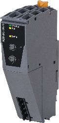
X20BC0073Description:
- Fieldbus: CAN bus
- Automatic firmware update via the fieldbus
- Integrated I/O access in B&R Automation Studio
- Integrated terminating resistor
The bus controller makes it possible to connect X2X Link I/O nodes to CAN I/O. CAN I/O is a transfer protocol based on standard CAN bus that is fully integrated in the B&R system.
Up to 43 logic I/O modules can be connected to the bus controller. Up to 16 of them can be analog modules.
With multifunction modules, the bus controller supports only the default function model in the event of automatic configuration by the bus controller (see the respective module description).
Mandatory Accessories
System modules for bus controllers
| X20BB80 | X20 bus controller, 1 CAN I/O interface, order 1x terminal block TB2105 separately! Order bus base, power supply module and terminal block separately! |
| X20PS9400 | X20 bus controller, 1 CAN I/O interface, order 1x terminal block TB2105 separately! Order bus base, power supply module and terminal block separately! |
| X20PS9402 | X20 bus controller, 1 CAN I/O interface, order 1x terminal block TB2105 separately! Order bus base, power supply module and terminal block separately! |
Terminal blocks
| 0TB2105.9010 | X20 bus controller, 1 CAN I/O interface, order 1x terminal block TB2105 separately! Order bus base, power supply module and terminal block separately! |
| 0TB2105.9110 | X20 bus controller, 1 CAN I/O interface, order 1x terminal block TB2105 separately! Order bus base, power supply module and terminal block separately! |
| X20TB12 | X20 bus controller, 1 CAN I/O interface, order 1x terminal block TB2105 separately! Order bus base, power supply module and terminal block separately! |
| Automation Studio HW Upgrades | Version (Date) | Download |
|---|---|---|
| V2.6 HW Upgrade (X20BC0073) | EXE / 1 MB | |
| V2.6 HW Upgrade (X20BC0073a) | EXE / 581 KB | |
| V3.0 HW Upgrade (X20BC0073) | EXE / 2 MB | |
| V3.0 HW Upgrade (X20BC0073a) | EXE / 581 KB | |
| V4.0 HW Upgrade (X20BC0073) | EXE / 1 MB |
| Documentation | Version (Date) | Download |
|---|---|---|
| Data sheet X20BC0073 | PDF / 3 MB | |
| X20 Package leaflet ATEX/CSA | PDF / 2 MB | |
| X20 System User´s Manual | PDF / 49 MB |
| E-CAD (Electro or EPLAN Templates) | Version (Date) | Download |
|---|---|---|
| X20 EPLAN P8 from V2.4 | EXE / 160 MB |
| M-CAD (Mechan. Templates) | Version (Date) | Download |
|---|---|---|
| 3D File DXF/STEP X20 Bus Controller CAN/DeviceNet | ZIP / 28 KB | |
| Dimensions PDF X20 Bus Controller CAN/DeviceNet | PDF / 4 KB |