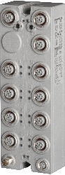
Short description
| Bus controller | PROFINET IO slave |
General information
| B&R ID code | |
| Bus controller | 0xC5E8 |
| Internal I/O module | 0xD9CB |
| Diagnostics | |
| Outputs | Yes, using LED status indicator and software |
| I/O power supply | Yes, using LED status indicator and software |
| Connection type | |
| Fieldbus | M12, D-coded |
| X2X Link | M12, B-coded |
| Inputs/Outputs | 8x M12, A-coded |
| I/O power supply | M8, 4-pin |
| Power consumption | |
| Fieldbus | 4.2 W |
| Internal I/O | 2.5 W |
| X2X Link power supply | 24.3 W at maximum power output for connected I/O modules |
| Certifications | |
| CE | Yes |
| UKCA | Yes |
| CRA (Cyber Resilience Act) | In preparation |
| ATEX |
Zone 2, II 3G Ex nA IIA T5 Gc IP67, Ta = 0 - Max. 60°C TÜV 05 ATEX 7201X |
| UL |
cULus E115267 Industrial control equipment |
| HazLoc |
cCSAus 244665 Process control equipment for hazardous locations Class I, Division 2, Groups ABCD, T5 |
| Inputs/Outputs | 16 digital channels, configurable as inputs or outputs using software, inputs with additional functions |
| Insulation voltage between channel and bus | 500 Veff |
| Nominal voltage | 24 VDC |
| Sensor/Actuator power supply | 0.5 A summation current |
| Status indicators | I/O function per channel, supply voltage, bus function |
| Power output | 15 W X2X Link power supply for I/O modules |
Interfaces
I/O power supply
Sensor/Actuator power supply
| Voltage | I/O power supply minus voltage drop for short-circuit protection |
| Voltage drop for short-circuit protection at 0.5 A | Max. 2 VDC |
| Summation current | Max. 0.5 A |
| Short-circuit proof | Yes |
Digital inputs
| Input filter | |
| Hardware | ≤10 μs (channels 1 to 4) / ≤70 µs (channels 5 to 16) |
| Software | Default 0 ms, configurable between 0 and 25 ms in 0.2 ms intervals |
| Switching threshold | |
| Low | <5 VDC |
| High | >15 VDC |
| Input characteristics per EN 61131-2 | Type 1 |
| Input voltage | 18 to 30 VDC |
| Input current at 24 VDC | Typ. 4 mA |
| Input circuit | Sink |
| Input resistance | Typ. 6 kΩ |
| Additional functions | 50 kHz event counting, gate measurement |
Event counters
| Quantity | 2 |
| Signal form | Square wave pulse |
| Evaluation | Each negative edge, cyclic counter |
| Input frequency | Max. 50 kHz |
| Counter 1 | Input 1 |
| Counter 2 | Input 3 |
| Counter frequency | Max. 50 kHz |
| Counter size | 16-bit |
Gate time measurement
| Counter frequency | |
| Internal | 48 MHz, 3 MHz, 187.5 kHz |
| Quantity | 1 |
| Signal form | Square wave pulse |
| Evaluation | Positive edge - Negative edge |
| Counter size | 16-bit |
| Length of pause between pulses | ≥100 µs |
| Pulse length | ≥20 µs |
| Supported inputs | Input 2 |
Digital outputs
| Switching delay | |
| 0 → 1 | <400 µs |
| 1 → 0 | <400 µs |
| Switching frequency | |
| Resistive load | Max. 100 Hz |
| Inductive load | See section "Switching inductive loads". |
| Variant | Current-sourcing FET |
| Switching voltage | I/O power supply minus residual voltage |
| Nominal output current | 0.5 A |
| Total nominal current | 8 A |
| Output circuit | Source |
| Output protection | Thermal shutdown in the event of overcurrent or short circuit, integrated protection for switching inductive loads, reverse polarity protection of the output power supply |
| Diagnostic status | Output monitoring with 10 ms delay |
| Leakage current when the output is switched off | 5 µA |
| Switching on after overload shutdown | Approx. 10 ms (depends on the module temperature) |
| Residual voltage | <0.3 V at 0.5 A nominal current |
| Peak short-circuit current | <12 A |
| Braking voltage when switching off inductive loads | 50 VDC |
Electrical properties
| Electrical isolation |
Bus isolated from PROFINET and channel Channel not isolated from channel |
Operating conditions
| Mounting orientation | |
| Any | Yes |
| Installation elevation above sea level | |
| 0 to 2000 m | No limitation |
| >2000 m | Reduction of ambient temperature by 0.5°C per 100 m |
| Degree of protection per EN 60529 | IP67 |
Ambient conditions
| Temperature | |
| Operation | -25 to 60°C |
| Derating | - |
| Storage | -40 to 85°C |
| Transport | -40 to 85°C |
Mechanical properties
| Dimensions | |
| Width | 53 mm |
| Height | 155 mm |
| Depth | 42 mm |
| Torque for connections | |
| M8 | Max. 0.4 Nm |
| M12 | Max. 0.6 Nm |
| Weight | 350 g |
Material number:
X67BCE321.L12Description:
- Fieldbus: PROFINET IO
- I/O configuration via the fieldbus
- Conformance Class B (RT)
- 1 ms minimum cycle time
- Integrated switch for wiring multiple slaves
- 100 Mbit/s full-duplex mode
- Up to 1440 bytes of input data and up to 1440 bytes of output data are possible
- Integrated website
- PROFINET diagnostics and module diagnostics during runtime from within the master environment
- Module and switch diagnostics during runtime using the website or SNMP
- 16 digital channels, configurable as inputs or outputs
- Integrated connection for additional 253 modules via X2X Link
PROFINET (Process Field Network) is an Industrial Ethernet protocol. It uses TCP/IP and is real-time capable.
X67 modules or other modules that are based on X2X Link can be connected to the bus controller. Modular system configurations are optimally supported by PROFINET. Using the device description file (GSDML format), it is very easy to handle project configuration in the respective engineering tool from the manufacturer of the master device.
| Documentation | Version (Date) | Download |
|---|---|---|
| Data sheet X67BCE321.L12 | PDF / 2 MB | |
| PROFINET IO Bus Controller User's Manual | PDF / 7 MB | |
| X67 System User´s Manual | PDF / 19 MB |
| E-CAD (Electro or EPLAN Templates) | Version (Date) | Download |
|---|---|---|
| X67 EPLAN P8 from V2.4 | EXE / 105 MB |
| Fieldbus equipment description files | Version (Date) | Download |
|---|---|---|
| PROFINET Bus Controller GSD Package | ZIP / 2 MB |
| M-CAD (Mechan. Templates) | Version (Date) | Download |
|---|---|---|
| 3D File DXF/STEP X67 | ZIP / 3 MB |