Short description
| I/O module | 8 safe type A digital inputs, 4 pulse outputs, 24 VDC, SafeLOGIC-X technology |
General information
Safety characteristics
| Note | See section "Safety characteristics". |
Limit values for SafeDESIGNER application
I/O power supply
| Nominal voltage | 24 VDC |
| Voltage range | 24 VDC -15% / +20% |
| Integrated protective function | Reverse polarity protection |
Safe digital inputs
Pulse outputs
Operating conditions
| Mounting orientation | |
| Horizontal | Yes |
| Vertical | Yes |
| Installation elevation above sea level | 0 to 2000 m, no limitation |
| Degree of protection per EN 60529 | IP20 |
Ambient conditions
| Temperature | |
| Operation | |
| Horizontal mounting orientation | 0 to 60°C |
| Vertical mounting orientation | 0 to 50°C |
| Derating | See section "Derating". |
| Storage | -40 to 85°C |
| Transport | -40 to 85°C |
| Relative humidity | |
| Operation | 5 to 95%, non-condensing |
| Storage | 5 to 95%, non-condensing |
| Transport | 5 to 95%, non-condensing |
Mechanical properties
| Note |
Order 1x safety-keyed terminal block separately. Order 1x safety-keyed bus module (single-width) separately. |
| Pitch | 12.5+0.2 mm |
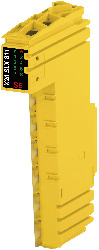
Material number:
X20SLX811Description:
- openSAFETY manager for up to 10 SafeNODEs
- Flexibly programmable using Automation Studio / SafeDESIGNER
- Innovative management of safe machine options (SafeOPTION)
- Parameter and configuration management
- 8 safe digital inputs
- 4 pulse outputs
- Sink circuit
- Software input filter configurable for each channel
The module is equipped with SafeLOGIC functionality that allows it to safely execute applications designed in SafeDESIGNER. The module can be used in safety-related applications up to PL e or SIL 3.
In addition, the module coordinates the safety-related communication of all modules involved in the application. In this context, the module also monitors the configuration of these modules and carries out autonomous parameter downloads to the modules whenever necessary. This guarantees a consistent and correct module configuration in the network from a safety standpoint in all scenarios involving module replacement and service. These services are performed in conjunction with Automation Runtime on the standard CPU.
In addition, SafeLOGIC-X products have the same I/O properties as the associated SafeIO products (X20SIx1x0).
Mandatory Accessories
Bus modules
Terminal blocks
| X20TB52 | X20 terminal block, 12-pin, safety-keyed |
| Automation Studio HW Upgrades | Version (Date) | Download |
|---|---|---|
| V4.0 HW Upgrade (X20SLX811) | EXE / 5 MB | |
| V4.1 HW Upgrade (X20SLX811) | EXE / 5 MB | |
| V4.2 HW Upgrade (X20SLX811) | EXE / 6 MB | |
| V4.6 HW Upgrade (X20SLX811) | EXE / 6 MB | |
| V6.0 HW Upgrade (X20SLX811) | EXE / 6 MB |
| Documentation | Version (Date) | Download |
|---|---|---|
| Data sheets SafeIO and SafeLogic | PDF / 29 MB | |
| Information sheet SafeLOGIC | PDF / 553 KB | |
| Integrated safety technology user's manual | PDF / 59 MB | |
| X20 System User´s Manual | PDF / 49 MB |
| E-CAD (Electro or EPLAN Templates) | Version (Date) | Download |
|---|---|---|
| X20 EPLAN P8 from V2.4 | EXE / 160 MB |
| M-CAD (Mechan. Templates) | Version (Date) | Download |
|---|---|---|
| 3D file STEP X20 Safety module | ZIP / 854 KB |
| Tools / Utilities / Examples | Version (Date) | Download |
|---|---|---|
| Sistema (VDMA) library | ZIP / 5 KB |