Short description
| I/O module | 1 full bridge for controlling stepper motors |
General information
Motor output stage
Digital inputs
ABR incremental encoder
| Quantity | 1 |
| Encoder inputs | 5 V, symmetrical |
| Counter size | 16-bit |
| Input frequency | Max. 125 kHz |
| Evaluation | 4x |
| Open-circuit detection | Yes, differential detection |
Electrical properties
| Electrical isolation | Channel isolated from bus and channel isolated from I/O power supply |
Operating conditions
| Mounting orientation | |
| Horizontal | Yes |
| Vertical | Yes |
| Installation elevation above sea level | |
| 0 to 2000 m | No limitation |
| >2000 m | Reduction of ambient temperature by 0.5°C per 100 m |
| Degree of protection per EN 60529 | IP20 |
Ambient conditions
| Temperature | |
| Operation | |
| Horizontal mounting orientation | -20 to +50°C |
| Vertical mounting orientation | -20 to +40°C |
| Derating | See section "Derating". |
| Storage | -25 to +80°C |
| Transport | -25 to +80°C |
| Relative humidity | |
| Operation | 5 to 95%, non-condensing |
| Storage | 5 to 95%, non-condensing |
| Transport | 5 to 95%, non-condensing |
Mechanical properties
| Note |
Order 1x terminal block X20TB12 separately. Order 1x bus module X20BM31 separately. |
| Pitch | 25+0.2 mm |
Material number:
X20SM1444-1Description:
- 1 stepper motor, 24 to 48 VDC ±25%, 5 A (10 A peak)
- Resolution of current values at 1%
- Boost, nominal and holding current separately configurable
- Sensorless, load-dependent current control
- Integrated motor detection
- 256 microsteps per step
- Stall detection
- Complete integration in Automation Studio and CNC applications
- R+ and R- also configurable as digital inputs
- Open circuit detection with 5 V differential ABR interface
- Input ramp limit at max. 12.5 A
- Function model "Ramp" based on CANopen communication profile DS402
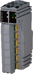
The stepper motor module is used to control stepper motors with a nominal voltage of 24 to 48 VDC (±25%) at a motor current up to 5 A (10 A peak). ABR outputs R+ and R- can also be used as digital inputs.
Due to the individual adjustment of the coil currents, the motor is only operated with the current it actually needs. This simplifies the selection of the available motors and prevents unnecessary heating. Because this affects energy consumption and thermal load, the effects are positive on the service life of the complete system. Complete flexibility is achieved through the use of independently adjustable holding, maximum and nominal current values. The current for microsteps is automatically adjusted to the configured current values.
In addition, the module contains a sensorless, load-dependent current control. Depending on the operating situation and load, the module regulates the current downwards. Energy savings up to 75% are possible in this way.
The automatic motor identification system is an enormous help during standstills. The stepper motor modules can identify the connected motors using their coil characteristics and generate feedback in the form of an analog value. This makes it possible to detect not only wiring errors, but also incorrect motor types being used mistakenly. "Stall detection" is integrated to analyze the motor load. Detection of the stall is defined via a configurable threshold. This allows an overload or motor standstill to be detected precisely in many different types of applications.
Mandatory Accessories
Bus modules
| X20BM31 | X20 stepper motor module, module power supply 24 to 48 VDC ±25%, with current reduction function, 1 motor connection, 5 A continuous current, 10 A peak current, 5 V ABR, quick stop / enable, NetTime function, double-width module |
Terminal blocks
| X20TB12 | X20 stepper motor module, module power supply 24 to 48 VDC ±25%, with current reduction function, 1 motor connection, 5 A continuous current, 10 A peak current, 5 V ABR, quick stop / enable, NetTime function, double-width module |
| Aktualizacja Automation Studio HW | Version (Date) | Download |
|---|---|---|
| V4.0 HW Upgrade (X20SM1444-1) | EXE / 2 MB | |
| V6.0 HW Upgrade (X20SM1444-1) | EXE / 2 MB |
| Dokumentacja | Version (Date) | Download |
|---|---|---|
| Data sheet X20SM1444-1 | PDF / 2 MB | |
| X20 System User´s Manual | PDF / 49 MB |
| E-CAD (szablony Electro lub EPLAN) | Version (Date) | Download |
|---|---|---|
| X20 EPLAN P8 from V2.4 | EXE / 160 MB |
| M-CAD (Mechan. szablony) | Version (Date) | Download |
|---|---|---|
| 3D File DXF/STEP X20 Electronic module | ZIP / 10 KB | |
| 3D File STEP X20 I/O-Slice | ZIP / 872 KB | |
| Dimensions PDF X20 Electronic module | PDF / 3 KB |