Short description
| I/O module | 4 inputs for Pt1000 resistance temperature measurement, analog inputs, PWM signal outputs, 1-wire connections |
General information
| Electrical isolation | |
| Digital - Digital | No |
| Digital - Analog | No |
| Certifications | |
| UN ECE-R10 | Yes |
| CE | Yes |
| UKCA | Yes |
| CRA (Cyber Resilience Act) | In preparation |
| B&R ID code | 0xEC23 |
| Status indicators | - |
| Diagnostics | |
| Power consumption | 0.6 W |
Multi-function inputs
| Multifunction resistance measurement inputs (MF-AT) | |
| Quantity | 4 |
| Functions | Resistance measurement input Pt1000, digital input, sink/source circuit, analog input 0 to 10 V, 0 to 32 V, 0 to 20 mA, PWM signal output high-side, configurable per channel |
Digital inputs
| Input filter | |
| Hardware | 500 μs at switching threshold = 50% supply voltage |
| Software | Default 1 ms, configurable between 0 and 25 ms in 0.2 ms increments |
| Quantity | 0 to 4, depends on the use of multifunction inputs/outputs |
| Input voltage | 9 to 32 VDC |
| Input current at 24 VDC | Typ. 2.4 mA |
| Input circuit | Sink/Source, configurable |
| Input resistance | 10 kΩ |
| Input delay | <0.5 ms (at 200 μs sampling rate) |
| Switching threshold | Fixed or ratiometric, configurable |
Analog inputs
Resistance measurement temperature inputs
PWM output
| Switching delay | |
| 0 → 1 | <1 µs |
| 1 → 0 | <1 µs |
| Switching frequency | |
| Resistive load | Max. 1 kHz |
| Quantity | 0 to 4, depends on the use of multifunction inputs/outputs |
| Nominal voltage | 12 / 24 VDC |
| Switching voltage | 9 to 32 V |
| Voltage drop | Max. 3.5 V |
| Nominal current | 10 mA |
| Output circuit | Source |
| Output protection | Thermal current limiting at 50 mA on short circuit |
| Variant | High-side FET |
| Leakage current when the output is switched off | <5 μA |
| Residual voltage | <2.5 V at 10 mA nominal current |
| Peak short-circuit current | 250 mA |
Ambient conditions
Mechanical properties
| Dimensions | |
| Width | 47 mm |
| Length | 95 mm |
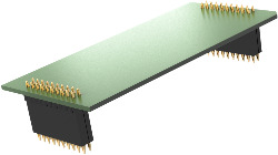
型番:
X90AT910.04-00説明:
- 9 to 32 VDC
- 4 current, voltage, temperature or digital inputs or PWM outputs
- Temperature measurement
- X2X Link
The AT option board offers 4 additional channels that can be used for current, voltage or temperature measurement. It is also possible to use the analog inputs as PWM signal outputs or digital inputs (with toggling between sink mode and source mode). Communication to the mainboard is made possible via X2X Link.
| Automation Studio HW アップグレード | バージョン (日付) | ダウンロード |
|---|---|---|
| V4.3 HW Upgrade (X90AT910.04-00) | EXE / 892 KB |
| E-CAD(ElectroまたはEPLANテンプレート) | バージョン (日付) | ダウンロード |
|---|---|---|
| X90 EPLAN P8 from V2.4 | EXE / 69 MB |
| ドキュメンテーション | バージョン (日付) | ダウンロード |
|---|---|---|
| Datasheet X90AT910.xx-00 | PDF / 604 KB | |
| X90 mobile System User´s Manual | PDF / 27 MB |