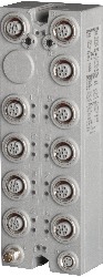
Short description
| Bus controller | Modbus TCP/UDP slave |
General information
| B&R ID code | |
| Bus controller | 0xAD3C |
| Internal I/O module | 0xBD76 |
| Diagnostics | |
| Outputs | Yes, using LED status indicator and software |
| I/O power supply | Yes, using LED status indicator and software |
| Connection type | |
| Fieldbus | M12, D-coded |
| X2X Link | M12, B-coded |
| Inputs/Outputs | 8x M12, A-coded |
| I/O power supply | M8, 4-pin |
| Power consumption | |
| Fieldbus | 4.2 W |
| Internal I/O | 2.5 W |
| X2X Link power supply | 24.3 W at maximum power output for connected I/O modules |
| Certifications | |
| CE | Yes |
| UKCA | Yes |
| CRA (Cyber Resilience Act) | Evaluation ongoing |
| ATEX |
Zone 2, II 3G Ex nA IIA T5 Gc IP67, Ta = 0 - Max. 60°C TÜV 05 ATEX 7201X |
| UL |
cULus E115267 Industrial control equipment |
| HazLoc |
cCSAus 244665 Process control equipment for hazardous locations Class I, Division 2, Groups ABCD, T5 |
| KC | Yes |
| Inputs/Outputs | 16 digital channels, configurable as inputs or outputs using Automation Studio or data point, inputs with additional functions |
| Insulation voltage between channel and bus | 500 Veff |
| Nominal voltage | 24 VDC |
| Sensor/Actuator power supply | 0.5 A summation current |
| Status indicators | I/O function per channel, supply voltage, bus function |
| Power output | 15 W X2X Link power supply for I/O modules |
Interfaces
I/O power supply
Sensor/Actuator power supply
| Voltage | I/O power supply minus voltage drop for short-circuit protection |
| Voltage drop for short-circuit protection at 0.5 A | Max. 2 VDC |
| Summation current | Max. 0.5 A |
| Short-circuit proof | Yes |
Digital inputs
| Input filter | |
| Hardware | ≤10 μs (channels 1 to 4) / ≤70 µs (channels 5 to 16) |
| Software | Default 0 ms, configurable between 0 and 25 ms in 0.2 ms intervals |
| Switching threshold | |
| Low | <5 VDC |
| High | >15 VDC |
| Input characteristics per EN 61131-2 | Type 1 |
| Input voltage | 18 to 30 VDC |
| Input current at 24 VDC | Typ. 4 mA |
| Input circuit | Sink |
| Input resistance | Typ. 6 kΩ |
| Additional functions | 50 kHz event counting, gate measurement |
Event counters
| Quantity | 2 |
| Signal form | Square wave pulse |
| Evaluation | Each negative edge, cyclic counter |
| Input frequency | Max. 50 kHz |
| Counter 1 | Input 1 |
| Counter 2 | Input 3 |
| Counter frequency | Max. 50 kHz |
| Counter size | 16-bit |
Gate time measurement
| Counter frequency | |
| Internal | 48 MHz, 3 MHz, 187.5 kHz |
| Quantity | 1 |
| Signal form | Square wave pulse |
| Evaluation | Positive edge - Negative edge |
| Counter size | 16-bit |
| Length of pause between pulses | ≥100 µs |
| Pulse length | ≥20 µs |
| Supported inputs | Input 2 or input 4 |
Digital outputs
| Switching delay | |
| 0 → 1 | <400 µs |
| 1 → 0 | <400 µs |
| Switching frequency | |
| Resistive load | Max. 100 Hz |
| Inductive load | See section "Switching inductive loads". |
| Variant | Current-sourcing FET |
| Switching voltage | I/O power supply minus residual voltage |
| Nominal output current | 0.5 A |
| Total nominal current | 8 A |
| Output circuit | Source |
| Output protection | Thermal shutdown in the event of overcurrent or short circuit, integrated protection for switching inductive loads, reverse polarity protection of the output power supply |
| Diagnostic status | Output monitoring with 10 ms delay |
| Leakage current when the output is switched off | 5 µA |
| Switching on after overload shutdown | Approx. 10 ms (depends on the module temperature) |
| Residual voltage | <0.3 V at 0.5 A nominal current |
| Peak short-circuit current | <12 A |
| Braking voltage when switching off inductive loads | 50 VDC |
Electrical properties
| Electrical isolation |
Bus isolated from channel Modbus not isolated from bus and channel not isolated from channel |
Operating conditions
| Mounting orientation | |
| Any | Yes |
| Installation elevation above sea level | |
| 0 to 2000 m | No limitation |
| >2000 m | Reduction of ambient temperature by 0.5°C per 100 m |
| Degree of protection per EN 60529 | IP67 |
Ambient conditions
| Temperature | |
| Operation | -25 to 60°C |
| Derating | - |
| Storage | -40 to 85°C |
| Transport | -40 to 85°C |
Mechanical properties
| Dimensions | |
| Width | 53 mm |
| Height | 155 mm |
| Depth | 42 mm |
| Torque for connections | |
| M8 | Max. 0.4 Nm |
| M12 | Max. 0.6 Nm |
| Weight | 350 g |
型番:
X67BCJ321.L12説明:
- Fieldbus: Modbus/TCP, Modbus/UDP
- Integrated 2-port switch for efficient cabling
- I/O configuration via the fieldbus
- DHCP-capable
- Response time: <1 to 8 ms (depends on the load on the integrated switch)
- Check validity of command sequences before execution
- 16 digital channels, configurable as inputs or outputs
- M12 connection type
- Integrated connection to local expansions via X2X Link for 250 additional modules
- Configurable I/O cycle (0.5 to 4 ms)
Established in 1979, the Modbus protocol has approved the use of Ethernet with both Modbus TCP and Modbus/UDP. Today, Modbus TCP is an open Internet draft standard introduced by Schneider Automation to the Internet Engineering Task Force (IETF), the organization responsible for Internet standardization. The Modbus services and object model have been preserved since the original version and left unchanged for use with the TCP/IP transmission medium.
Modbus/UDP differs from Modbus TCP in that it uses connectionless communication via UDP/IP. The advantages of faster and easier communication with UDP/IP also brings with it the disadvantage of requiring error detection and correction in the application layer.
This bus controller makes it possible to connect X2X Link I/O nodes to Modbus via Ethernet. The bus controller can be operated on B&R controllers through the use of Automation Studio or on third-party systems with Modbus TCP or -UDP master functionality.
With multifunction modules, the bus controller supports only the default function model in the event of automatic configuration by the bus controller (see the respective module description).
All other function models are supported when configured accordingly in Automation Studio V4.3 or later.
Automation Studio kann kostenlos von der B&R Webseite www.br-automation.com heruntergeladen werden. Die Evaluierungslizenz darf unentgeltlich zur Erstellung vollständiger Konfigurationen der Feldbus Bus Controller benützt werden.
| Automation Studio HW アップグレード | バージョン (日付) | ダウンロード |
|---|---|---|
| V3.0 HW Upgrade (X67BCJ321.L12) | EXE / 403 KB | |
| V4.3 HW Upgrade (X67BCJ321.L12) | EXE / 2 MB |
| E-CAD(ElectroまたはEPLANテンプレート) | バージョン (日付) | ダウンロード |
|---|---|---|
| X67 EPLAN P8 from V2.4 | EXE / 105 MB |
| Fieldbus機器の説明ファイル | バージョン (日付) | ダウンロード |
|---|---|---|
| Modbus Mapping Tool | ZIP / 480 KB | |
| ModbusTCP Toolbox | ZIP / 4 MB |
| M-CAD (Mechan.Templates) | バージョン (日付) | ダウンロード |
|---|---|---|
| STEP File X67BCx321.L12 | ZIP / 1 MB |
| ドキュメンテーション | バージョン (日付) | ダウンロード |
|---|---|---|
| Datasheet X67BCJ321.L12 | PDF / 2 MB | |
| Modbus/TCP Bus Controller User's manual | PDF / 22 MB | |
| X67 System User´s Manual | PDF / 19 MB |