Short description
| Communication module | CANopen slave |
General information
| Diagnostics | |
| Module status | Yes, using LED status indicator and software |
| Network status | Yes, using LED status indicator and software |
| Data transfer | Yes, using LED status indicator |
| Terminating resistor | Yes, using LED status indicator |
| Certifications | |
| CE | Yes |
| UKCA | Yes |
| CRA (Cyber Resilience Act) | In preparation |
| ATEX |
Zone 2, II 3G Ex nA nC IIA T5 Gc IP20, Ta (see X20 user's manual) FTZÚ 09 ATEX 0083X |
| UL |
cULus E115267 Industrial control equipment |
| HazLoc |
cCSAus 244665 Process control equipment for hazardous locations Class I, Division 2, Groups ABCD, T5 |
| DNV |
Temperature: B (0 to 55°C) Humidity: B (up to 100%) Vibration: B (4 g) EMC: B (bridge and open deck) |
| CCS | Yes |
| LR | ENV1 |
| KR | Yes |
| ABS | Yes |
| BV |
EC33B Temperature: 5 - 55°C Vibration: 4 g EMC: Bridge and open deck |
| KC | Yes |
| B&R ID code | 0xA70B |
| Status indicators | Module status, network status, data transfer, terminating resistor |
| Power consumption | 1.1 W |
| Additional power dissipation caused by actuators (resistive) [W] | - |
Interfaces
| Interface IF1 | |
| Fieldbus | CANopen slave |
| Variant | 5-pin male multipoint connector |
| Max. distance | 1000 m |
| Transfer rate | Max. 1 Mbit/s |
| Terminating resistor | Integrated in module |
| Controller | netX100 |
Electrical properties
| Electrical isolation | PLC isolated from CANopen (IF1) |
Operating conditions
| Mounting orientation | |
| Horizontal | Yes |
| Vertical | Yes |
| Installation elevation above sea level | |
| 0 to 2000 m | No limitation |
| >2000 m | Reduction of ambient temperature by 0.5°C per 100 m |
| Degree of protection per EN 60529 | IP20 |
Ambient conditions
| Temperature | |
| Operation | |
| Horizontal mounting orientation | -25 to 60°C |
| Vertical mounting orientation | -25 to 50°C |
| Derating | - |
| Storage | -40 to 85°C |
| Transport | -40 to 85°C |
| Relative humidity | |
| Operation | 5 to 95%, non-condensing |
| Storage | 5 to 95%, non-condensing |
| Transport | 5 to 95%, non-condensing |
Mechanical properties
| Note | Order 1x terminal block TB2105 separately. |
| Slot | In the X20 PLC and expandable bus controller X20BC1083 |
Référence produit:
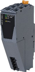
X20IF1043-1Description:
- CANopen slave
- Integrated terminating resistor
The interface module is equipped with a CANopen (slave) interface. This allows the B&R system (I/O modules, POWERLINK, etc.) to be connected to systems from other manufacturers and makes it possible to quickly and easily transfer data in both directions.
The interface module can be operated in the X20 controllers or in the expandable X20BC1083 POWERLINK bus controller.
Accessoires obligatoires
Terminal blocks
| 0TB2105.9010 | X20 interface module, for DTM configuration, 1 CANopen slave interface, electrically isolated, order 1x terminal block TB2105 separately! |
| 0TB2105.9110 | X20 interface module, for DTM configuration, 1 CANopen slave interface, electrically isolated, order 1x terminal block TB2105 separately! |
| Automation Studio HW Upgrades | Version (date) | Téléchargement |
|---|---|---|
| V3.0 HW Upgrade (X20IF1043-1) | EXE / 639 Ko | |
| V3.0 HW Upgrade (X20IF1043-1) | EXE / 1 Mo | |
| V4.0 HW Upgrade (X20IF1043-1) | EXE / 2 Mo |
| Documentation | Version (date) | Téléchargement |
|---|---|---|
| Datasheet X20IF1043-1 | PDF / 3 Mo | |
| X20 Package leaflet ATEX/CSA | PDF / 2 Mo | |
| X20 System User´s Manual | PDF / 49 Mo |
| E-CAD (modèles Electro ou EPLAN) | Version (date) | Téléchargement |
|---|---|---|
| X20 EPLAN P8 from V2.4 | EXE / 160 Mo |
| Fichiers de description d'équipement bus de terrain | Version (date) | Téléchargement |
|---|---|---|
| X20IF1043-1 description file | ZIP / 18 Ko |
| M-CAD (modèles mécaniques) | Version (date) | Téléchargement |
|---|---|---|
| 3D File DXF/STEP X20 Interface module CAN/DeviceNet | ZIP / 946 Ko | |
| Dimensions PDF X20 Interface Module CAN/DeviceNet | PDF / 4 Ko |