Short description
| Potential distributor module | 12x 24 VDC at the terminals |
General information
Output I/O power supply
| Nominal output voltage | 24 VDC from the internal I/O power supply |
| Fuse | Integrated 6.3 A, slow-blow, can be replaced |
| Behavior on short circuit | Integrated fuse |
| Permissible contact load | 10 A |
Operating conditions
| Mounting orientation | |
| Horizontal | Yes |
| Vertical | Yes |
| Installation elevation above sea level | |
| 0 to 2000 m | No limitation |
| >2000 m | Reduction of ambient temperature by 0.5°C per 100 m |
| Degree of protection per EN 60529 | IP20 |
Ambient conditions
| Temperature | |
| Operation | |
| Horizontal mounting orientation | -25 to 60°C |
| Vertical mounting orientation | -25 to 50°C |
| Derating | - |
| Storage | -40 to 85°C |
| Transport | -40 to 85°C |
| Relative humidity | |
| Operation | 5 to 95%, non-condensing |
| Storage | 5 to 95%, non-condensing |
| Transport | 5 to 95%, non-condensing |
Mechanical properties
| Note |
Order 1x terminal block X20TB12 separately. Order 1x bus module X20BM11 separately. |
| Pitch | 12.5+0.2 mm |
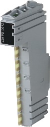
Référence produit:
X20PD0012Description:
- Integrated exchangeable microfuse
- Monitoring of the fuse
- Potential for routing as needed
The potential distributor module provides 12x 24 VDC (from the internal I/O supply) on the terminal connections and opens up additional wiring possibilities for actuators and sensors. The module is equipped with a replaceable microfuse between the 24 VDC potential on the terminal block and the X20 system I/O supply. The function of the fuse is monitored.
Accessoires obligatoires
| Automation Studio HW Upgrades | Version (date) | Téléchargement |
|---|---|---|
| V2.6 HW Upgrade (X20PD0012) | EXE / 1,014 Ko | |
| V3.0 HW Upgrade (X20PD0012) | EXE / 1 Mo | |
| V4.0 HW Upgrade (X20PD0012) | EXE / 666 Ko |
| Documentation | Version (date) | Téléchargement |
|---|---|---|
| Datasheet X20PD0012 | PDF / 736 Ko | |
| X20 Package leaflet ATEX/CSA | PDF / 2 Mo | |
| X20 System User´s Manual | PDF / 49 Mo |
| E-CAD (modèles Electro ou EPLAN) | Version (date) | Téléchargement |
|---|---|---|
| X20 EPLAN P8 from V2.4 | EXE / 160 Mo |
| M-CAD (modèles mécaniques) | Version (date) | Téléchargement |
|---|---|---|
| 3D File DXF/STEP X20 Electronic module | ZIP / 10 Ko | |
| 3D File STEP X20 I/O-Slice | ZIP / 872 Ko | |
| Dimensions PDF X20 Electronic module | PDF / 3 Ko |