Short description
| I/O module | 4-channel PWM motor bridge, 4 ABR incremental encoders |
General information
| Diagnostics | |
| Module run/error | Yes, using LED status indicator and software |
| Output | Yes, using LED status indicator and software |
| I/O power supply | Yes, using software |
| Power consumption | |
| External I/O 50 kHz | |
| 24 VDC | 3.3 W / channel |
| 48 VDC | 4.7 W / channel |
| 60 VDC | 5.4 W / channel |
| External I/O 10 kHz | |
| 24 VDC | 2.1 W / channel |
| 48 VDC | 2.4 W / channel |
| 60 VDC | 2.6 W / channel |
| External I/O 5 kHz | |
| 24 VDC | 2 W / channel |
| 48 VDC | 2.1 W / channel |
| 60 VDC | 2.2 W / channel |
| Bus | 0.01 W |
| Internal I/O | 2.4 W |
| Certifications | |
| CE | Yes |
| UKCA | Yes |
| CRA (Cyber Resilience Act) | In preparation |
| ATEX |
Zone 2, II 3G Ex nA nC IIA T5 Gc IP20, Ta (see X20 user's manual) FTZÚ 09 ATEX 0083X |
| UL |
cURus E225616 Power conversion equipment |
| HazLoc |
cCSAus 244665 Process control equipment for hazardous locations Class I, Division 2, Groups ABCD, T5 |
| KC | Yes |
| B&R ID code | 0xA177 |
| Status indicators | I/O function per channel, operating state, module status |
| Additional power dissipation caused by actuators (resistive) [W] | - |
Digital inputs
| Input filter | |
| Hardware | <5 µs |
| Software | - |
| Switching threshold | |
| Low | <5 VDC |
| High | >15 VDC |
| Quantity | 16 |
| Nominal voltage | 24 VDC |
| Input characteristics per EN 61131-2 | Type 1 |
| Input voltage | 24 VDC (-15% / +20%) |
| Input current at 24 VDC | Approx. 4 mA |
| Input circuit | Sink |
| Connection type | 1-wire connections |
| Input resistance | Typ. 6 kΩ |
| Additional functions | 4x ABR incremental encoder |
| Insulation voltage between channel and bus | 500 Veff |
ABR incremental encoder
| Quantity | 4 |
| Encoder inputs | 24 V, asymmetrical |
| Counter size | 16-bit |
| Input frequency | Max. 50 kHz |
| Evaluation | 4x |
| Signal form | Square wave pulse |
PWM output
Electrical properties
| Electrical isolation |
Channel isolated from bus Channel not isolated from channel |
Operating conditions
| Mounting orientation | |
| Horizontal | Yes |
| Installation elevation above sea level | |
| 0 to 2000 m | No limitation |
| >2000 m | Reduction of ambient temperature by 0.5°C per 100 m |
| Degree of protection per EN 60529 | IP20 |
Ambient conditions
| Temperature | |
| Operation | |
| Horizontal mounting orientation | 0 to 50°C |
| Vertical mounting orientation | Not permitted |
| Derating | - |
| Storage | -25 to 70°C |
| Transport | -25 to 70°C |
| Relative humidity | |
| Operation | 5 to 95%, non-condensing |
| Storage | 5 to 95%, non-condensing |
| Transport | 5 to 95%, non-condensing |
Mechanical properties
| Note |
Order 2x terminal block X20TB12 separately. Order 1x terminal block 0TB3103-7020 separately. |
| Pitch | 87.5+0.2 mm |
Material number:
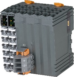
X20MM4456Description:
- 4x outputs (H bridge) with PWM control and 24 to 48 VDC ±25% supply
- 6 A nominal current (10 A max current)
- 15 Hz to 50 kHz frequency, 16-bit
- PWM resolution, 15-bit, + sign, minimum 10 ns
- Configurable dither
- 4x 4 inputs 24V, can be configured as ABR
- Sink connection
- 1-wire connections
The PMW motor bridge module is used to control 4 DC motors with a nominal voltage of 24 to 48 VDC ±25% at a nominal current up to 6 A.
Mandatory Accessories
Terminal blocks
| 0TB3103-7020 | X20 PWM motor module, 24 to 48 VDC ±25%, 4 PWM motor bridges, 6 A continuous current, 10 A peak current, 4x 4 digital inputs 24 VDC, sink, configurable as incremental encoder |
| X20TB12 | X20 PWM motor module, 24 to 48 VDC ±25%, 4 PWM motor bridges, 6 A continuous current, 10 A peak current, 4x 4 digital inputs 24 VDC, sink, configurable as incremental encoder |
| Automation Studio HW Upgrades | Version (Date) | Download |
|---|---|---|
| V2.6 HW Upgrade (X20MM4456) | EXE / 2 MB | |
| V3.0 HW Upgrade (X20MM4456) | EXE / 3 MB | |
| V4.0 HW Upgrade (X20MM4456) | EXE / 3 MB | |
| V6.0 HW Upgrade (X20MM4456) | EXE / 2 MB |
| Documentation | Version (Date) | Download |
|---|---|---|
| Datasheet X20MM4456 | PDF / 5 MB | |
| X20 System User´s Manual | PDF / 49 MB |
| E-CAD (Electro or EPLAN Templates) | Version (Date) | Download |
|---|---|---|
| X20 EPLAN P8 from V2.4 | EXE / 160 MB |
| M-CAD (Mechan. Templates) | Version (Date) | Download |
|---|---|---|
| 3D File STEP X20MM445x | ZIP / 995 KB |