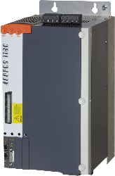
General information
Certifications
CE Yes
UKCA Yes
CRA (Cyber Resilience Act) Non-compliant
Functional safety Yes
UL cULus E225616
Power conversion equipment
KC Yes
B&R ID code 0x1282
Slots for plug-in modules 4
Mains connection
Permissible network configurations TT, TN
Mains input voltage 3x 400 VAC to 480 VAC ±10%
Frequency 50 / 60 Hz ±4%
Installed load Max. 17 kVA
Inrush current at 400 VAC 13 A
Switch-on interval >10 s
Integrated line filter per EN 61800-3, category C3 Yes
Power dissipation at device nominal power without braking resistor Approx. 500 W
DC bus connection
DC bus capacitance 940 µF
24 VDC power supply
Current consumption at 24 VDC
Mains input voltage applied -
Mains input voltage not applied Max. 2.8 A + Current for the motor holding brake + Current on the 24 VDC output
DC bus power supply unit
Switch-on voltage 455 VDC
Input voltage 24 VDC +25% / -20%
Input capacitance 40,000 µF
24 VDC output
Output voltage
Mains input voltage applied 22 to 24 VDC
Mains input voltage not applied 16.7 to 30 VDC
Output current Max. 0.5 A
Motor connection
Reduction of continuous current depending on ambient temperature
Mains input voltage: 400 VAC
Switching frequency 5 kHz No reduction
Switching frequency 10 kHz No reduction
Switching frequency 20 kHz No reduction
Mains input voltage: 480 VAC
Switching frequency 5 kHz No reduction
Switching frequency 10 kHz No reduction
Switching frequency 20 kHz No reduction
Reduction of continuous current depending on installation elevation
Starting at 500 m above sea level 1.9 Aeff per 1000 m
Protective measures
Overload protection Yes
Short-circuit and ground fault protection Yes
Terminal connection cross section
Flexible and fine-stranded wires
With wire end sleeve 0.5 to 6 mm²
Approbation data
UL/C-UL-US 20 to 8 AWG
CSA 20 to 8 AWG
Quantity 1
Continuous current 19 Aeff
Peak current 50 Aeff
Nominal switching frequency 10 kHz
Possible switching frequencies 5 / 10 / 20 kHz
Insulation stress of the connected motor per IEC TS 60034-25:2004 Limit value curve A
Max. motor line length 25 m
Max. output frequency 598 Hz
Motor holding brake connection
Response threshold for open-circuit monitoring Approx. 250 mA
Max. output current 1.5 A
Max. number of switching cycles Unlimited since implemented electronically
Braking resistor
Peak power int./ext. 14 / 40 kW
Continuous power int./ext. 0.4 / 8 kW
Minimum braking resistance (ext.) 15 Ω
Rated current of built-in fuse 12 A (fast-acting)
Limit switch and reference inputs
Electrical isolation
Input - ACOPOS Yes
Input - Input No
Input voltage
Nominal 24 VDC
Maximum 30 VDC
Switching threshold
Low <5 V
High >15 V
Quantity 3
Circuit Sink
Input current at nominal voltage Approx. 4 mA
Switching delay Max. 2.0 ms
Modulation compared to ground potential Max. ±38 V
Enable inputs
Electrical isolation
Input - ACOPOS Yes
Input voltage
Nominal 24 VDC
Maximum 30 VDC
Switching threshold
Low <5 V
High >15 V
Switching delay
Enable 0 → 1, ready for PWM Max. 100 µs
Enable 1 → 0, PWM off Max. 2.0 ms
Quantity 1
Circuit Sink
Input current at nominal voltage Approx. 30 mA
Modulation compared to ground potential Max. ±38 V
OSSD signal connections Not permitted
Trigger inputs
Electrical isolation
Input - ACOPOS Yes
Input - Input No
Input voltage
Nominal 24 VDC
Maximum 30 VDC
Switching threshold
Low <5 V
High >15 V
Switching delay
Rising edge 52 µs ±0.5 µs (digitally filtered)
Falling edge 53 µs ±0.5 µs (digitally filtered)
Quantity 2
Circuit Sink
Input current at nominal voltage Approx. 10 mA
Modulation compared to ground potential Max. ±38 V
Electrical properties
Energy efficiency (IE classification)
Power dissipation relative to continuous apparent power IE2 (10,25) 1.3%
IE2 (50,25) 1.4%
IE2 (10,50) 1.6%
IE2 (50,50) 1.7%
IE2 (90,50) 1.8%
IE2 (10,100) 2.3%
IE2 (50,100) 2.6%
IE2 (90,100) 3.1%
Nominal losses in standby mode 31.8 W
Discharge capacitance 3.1 µF
Operating conditions
Permissible mounting orientations
Hanging vertically Yes
Horizontal, face up Yes
Standing horizontally No
Installation elevation above sea level
Nominal 0 to 500 m
Maximum 2000 m
Pollution degree per EN 61800-5-1 2 (non-conductive pollution)
Overvoltage category per EN 61800-5-1 II
Degree of protection per EN 60529 IP20
Ambient conditions
Temperature
Operation
Nominal 5 to 40°C
Maximum 55°C
Storage -25 to 55°C
Transport -25 to 70°C
Relative humidity
Operation 5 to 85%
Storage 5 to 95%
Transport Max. 95% at 40°C
Mechanical properties
Dimensions
Width 200 mm
Height 375 mm
Depth 234 mm
Weight 10.1 kg
Material number:
8V1180.00-2
Description:
  • Modular mechanical design using plug-in modules
  • Integrated line filter
  • Integrated or optional external braking resistor
  • All connections are made using plug-in connectors
  • Integrated electronic restart inhibit
ACOPOS servo drive, 3x 400-480 V, 19 A, 9 kW, integrated line filter, braking resistor, DC bus power supply unit and electronic safe restart interlock
Included in delivery
Shield component sets
8X0020.00-1 ACOPOS servo drive, 3x 400-480 V, 19 A, 9 kW, integrated line filter, braking resistor, DC bus power supply unit and electronic safe restart interlock
Terminal block sets
8X0002.00-1 ACOPOS servo drive, 3x 400-480 V, 19 A, 9 kW, integrated line filter, braking resistor, DC bus power supply unit and electronic safe restart interlock
Optional Accessories
Braking resistors
8B0W0045H000.001-1 ACOPOS servo drive, 3x 400-480 V, 19 A, 9 kW, integrated line filter, braking resistor, DC bus power supply unit and electronic safe restart interlock
8B0W0079H000.000-1 ACOPOS servo drive, 3x 400-480 V, 19 A, 9 kW, integrated line filter, braking resistor, DC bus power supply unit and electronic safe restart interlock
8B0W0079H000.001-1 ACOPOS servo drive, 3x 400-480 V, 19 A, 9 kW, integrated line filter, braking resistor, DC bus power supply unit and electronic safe restart interlock
Plug-in modules
8AC110.60-3 ACOPOS servo drive, 3x 400-480 V, 19 A, 9 kW, integrated line filter, braking resistor, DC bus power supply unit and electronic safe restart interlock
8AC114.60-2 ACOPOS servo drive, 3x 400-480 V, 19 A, 9 kW, integrated line filter, braking resistor, DC bus power supply unit and electronic safe restart interlock
8AC120.60-1 ACOPOS servo drive, 3x 400-480 V, 19 A, 9 kW, integrated line filter, braking resistor, DC bus power supply unit and electronic safe restart interlock
8AC121.60-1 ACOPOS servo drive, 3x 400-480 V, 19 A, 9 kW, integrated line filter, braking resistor, DC bus power supply unit and electronic safe restart interlock
8AC122.60-3 ACOPOS servo drive, 3x 400-480 V, 19 A, 9 kW, integrated line filter, braking resistor, DC bus power supply unit and electronic safe restart interlock
8AC123.60-1 ACOPOS servo drive, 3x 400-480 V, 19 A, 9 kW, integrated line filter, braking resistor, DC bus power supply unit and electronic safe restart interlock
8AC125.60-1 ACOPOS servo drive, 3x 400-480 V, 19 A, 9 kW, integrated line filter, braking resistor, DC bus power supply unit and electronic safe restart interlock
8AC125.60-2 ACOPOS servo drive, 3x 400-480 V, 19 A, 9 kW, integrated line filter, braking resistor, DC bus power supply unit and electronic safe restart interlock
8AC125.61-2 ACOPOS servo drive, 3x 400-480 V, 19 A, 9 kW, integrated line filter, braking resistor, DC bus power supply unit and electronic safe restart interlock
8AC126.60-1 ACOPOS servo drive, 3x 400-480 V, 19 A, 9 kW, integrated line filter, braking resistor, DC bus power supply unit and electronic safe restart interlock
8AC130.60-1 ACOPOS servo drive, 3x 400-480 V, 19 A, 9 kW, integrated line filter, braking resistor, DC bus power supply unit and electronic safe restart interlock
8AC131.60-1 ACOPOS servo drive, 3x 400-480 V, 19 A, 9 kW, integrated line filter, braking resistor, DC bus power supply unit and electronic safe restart interlock
Undefined
8B0W0045H000.000-1 ACOPOS servo drive, 3x 400-480 V, 19 A, 9 kW, integrated line filter, braking resistor, DC bus power supply unit and electronic safe restart interlock
Automation Studio HW Upgrades Version (Date) Download
V3.0 HW Upgrade (8V1180.00-2) EXE / 392 KB
V4.0 HW Upgrade (8V1180.00-2) EXE / 279 KB
V6.0 HW Upgrade (8V1180.00-2) EXE / 352 KB
Certificates Version (Date) Download
ACOPOS KC certificates ZIP / 601 KB
E225616 UL Certificate of Compliance ACOPOS PDF / 242 KB
EU Declaration FS Servos ACOPOS PDF / 678 KB
EU Declaration Servos ACOPOS PDF / 271 KB
TÜV-certificate - function "Safe Pulse Disabling" ZIP / 423 KB
UK Declaration FS Servos ACOPOS PDF / 89 KB
UK Declaration Servos ACOPOS PDF / 109 KB
Documentation Version (Date) Download
ACOPOS User´s Manual PDF / 49 MB
Datasheet 8V1180.00-2 PDF / 2 MB
Safety Guidelines PDF / 1 MB
E-CAD (Electro or EPLAN Templates) Version (Date) Download
ACOPOS EPLAN P8 from V2.4 EXE / 23 MB
M-CAD (Mechan. Templates) Version (Date) Download
3D file STEP ACOPOS 1180/1320 ZIP / 2 MB
Tools / Utilities / Examples Version (Date) Download
Sistema (VDMA) library ZIP / 5 KB

Please choose country and language

B&R Logo