General information
| Support | |
| Dynamic node allocation (DNA) | Yes |
| Certifications | |
| CE | Yes |
| UKCA | Yes |
| CRA (Cyber Resilience Act) | In preparation |
| UL |
cULus E225616 Power conversion equipment |
| Slots for plug-in modules | 1 |
Mains connection
DC bus connection
24 VDC power supply
Motor connection
Motor holding brake connection
Braking resistor
| Protective measures | |
| Overload protection | No |
| Short-circuit and ground fault protection |
Short-circuit protection: Yes Ground fault protection: No |
| Peak power output | 45 kW |
| Continuous power | 4 kW |
| Minimum braking resistance (ext.) | 13 Ω |
| Max. line length | 3 m |
Fieldbus
| Type | POWERLINK V2 controlled node (CN) |
| Variant | 2x RJ45, shielded, 2-port hub |
| Line length | Max. 100 m between 2 stations (segment length) |
| Transfer rate | 100 Mbit/s |
Enable inputs
Encoder interfaces
Trigger inputs
| Electrical isolation | |
| Input - ACOPOS P3 | Yes |
| Input - Input | Yes |
| Input voltage | |
| Nominal | 24 VDC |
| Maximum | 30 VDC |
| Switching threshold | |
| Low | <5 V |
| High | >15 V |
| Switching delay | |
| Rising edge | <51 µs |
| Falling edge | <52 µs |
| Terminal connection cross section | |
| Flexible and fine-stranded wires | |
| With wire end sleeve | 0.25 to 2.5 mm² |
| Approbation data | |
| UL/C-UL-US | 26 to 12 AWG |
| CSA | 26 to 12 AWG |
| Quantity | 2 |
| Circuit | Sink |
| Input current at nominal voltage | 7 mA |
| Modulation compared to ground potential | Max. ±38 V |
| Max. line length | 100 m |
Temperature sensor connection
| Quantity | 1 |
| Resistance range | 500 Ω to 5 kΩ |
Support
| Motion system | |
| mapp Motion | 5.03.0 and higher |
| ACP10/ARNC0 | 3.17.0 and higher |
Electrical properties
Operating conditions
Ambient conditions
Mechanical properties
| Dimensions | |
| Depth | |
| Wall mounting | 258.5 mm (with 8EXA front cover: 261 mm) |
| Width | 133 mm |
| Height | 374 mm |
| Weight | 8 kg |
Material number:
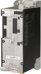
8EI044HWS10.XXXX-1Description:
ACOPOS P3 servo drive, 1 digital multi-standard encoder interface per axis, 3x 200-480 VAC, 44 A, 1 axis, wall mounting
Optional Accessories
Display modules
| 8EAD0000.000-1 | ACOPOS P3 servo drive, 1 digital multi-standard encoder interface per axis, 3x 200-480 VAC, 44 A, 1 axis, wall mounting |
Front covers
| 8EXA300.0010-00 | ACOPOS P3 servo drive, 1 digital multi-standard encoder interface per axis, 3x 200-480 VAC, 44 A, 1 axis, wall mounting |
| 8EXA300.0020-00 | ACOPOS P3 servo drive, 1 digital multi-standard encoder interface per axis, 3x 200-480 VAC, 44 A, 1 axis, wall mounting |
Line filters passive
| 8B0F0160H000.000-1 | ACOPOS P3 servo drive, 1 digital multi-standard encoder interface per axis, 3x 200-480 VAC, 44 A, 1 axis, wall mounting |
| 8B0F0300H000.000-1 | ACOPOS P3 servo drive, 1 digital multi-standard encoder interface per axis, 3x 200-480 VAC, 44 A, 1 axis, wall mounting |
| 8B0F0550H000.000-1 | ACOPOS P3 servo drive, 1 digital multi-standard encoder interface per axis, 3x 200-480 VAC, 44 A, 1 axis, wall mounting |
Plug-in modules
| 8EAC0122.001-1 | ACOPOS P3 servo drive, 1 digital multi-standard encoder interface per axis, 3x 200-480 VAC, 44 A, 1 axis, wall mounting |
| 8EAC0130.000-1 | ACOPOS P3 servo drive, 1 digital multi-standard encoder interface per axis, 3x 200-480 VAC, 44 A, 1 axis, wall mounting |
| 8EAC0150.001-1 | ACOPOS P3 servo drive, 1 digital multi-standard encoder interface per axis, 3x 200-480 VAC, 44 A, 1 axis, wall mounting |
| 8EAC0151.001-1 | ACOPOS P3 servo drive, 1 digital multi-standard encoder interface per axis, 3x 200-480 VAC, 44 A, 1 axis, wall mounting |
| 8EAC0152.001-1 | ACOPOS P3 servo drive, 1 digital multi-standard encoder interface per axis, 3x 200-480 VAC, 44 A, 1 axis, wall mounting |
Shield component sets
| 8SCSE01.0200-00 | ACOPOS P3 servo drive, 1 digital multi-standard encoder interface per axis, 3x 200-480 VAC, 44 A, 1 axis, wall mounting |
| 8SCSE01.0300-00 | ACOPOS P3 servo drive, 1 digital multi-standard encoder interface per axis, 3x 200-480 VAC, 44 A, 1 axis, wall mounting |
| 8SCSE02.0100-00 | ACOPOS P3 servo drive, 1 digital multi-standard encoder interface per axis, 3x 200-480 VAC, 44 A, 1 axis, wall mounting |
| 8SCSE02.0200-00 | ACOPOS P3 servo drive, 1 digital multi-standard encoder interface per axis, 3x 200-480 VAC, 44 A, 1 axis, wall mounting |
Terminal blocks
| 8TB2104.2210-00 | ACOPOS P3 servo drive, 1 digital multi-standard encoder interface per axis, 3x 200-480 VAC, 44 A, 1 axis, wall mounting |
| 8TB2104.2210-50 | ACOPOS P3 servo drive, 1 digital multi-standard encoder interface per axis, 3x 200-480 VAC, 44 A, 1 axis, wall mounting |
| 8TB2104.223L-00 | ACOPOS P3 servo drive, 1 digital multi-standard encoder interface per axis, 3x 200-480 VAC, 44 A, 1 axis, wall mounting |
| 8TB2204.2210-50 | ACOPOS P3 servo drive, 1 digital multi-standard encoder interface per axis, 3x 200-480 VAC, 44 A, 1 axis, wall mounting |
| 8TB3102.222C-20 | ACOPOS P3 servo drive, 1 digital multi-standard encoder interface per axis, 3x 200-480 VAC, 44 A, 1 axis, wall mounting |
| 8TB3202.222C-40 | ACOPOS P3 servo drive, 1 digital multi-standard encoder interface per axis, 3x 200-480 VAC, 44 A, 1 axis, wall mounting |
| 8TB4103.222A-10 | ACOPOS P3 servo drive, 1 digital multi-standard encoder interface per axis, 3x 200-480 VAC, 44 A, 1 axis, wall mounting |
| 8TB4104.222L-10 | ACOPOS P3 servo drive, 1 digital multi-standard encoder interface per axis, 3x 200-480 VAC, 44 A, 1 axis, wall mounting |
| 8TB4104.224G-10 | ACOPOS P3 servo drive, 1 digital multi-standard encoder interface per axis, 3x 200-480 VAC, 44 A, 1 axis, wall mounting |
| 8TB4104.227F-10 | ACOPOS P3 servo drive, 1 digital multi-standard encoder interface per axis, 3x 200-480 VAC, 44 A, 1 axis, wall mounting |
Terminal set
| 8EZI044HS1.2201-0 | ACOPOS P3 servo drive, 1 digital multi-standard encoder interface per axis, 3x 200-480 VAC, 44 A, 1 axis, wall mounting |
| 8EZI044HS1.2302-0 | ACOPOS P3 servo drive, 1 digital multi-standard encoder interface per axis, 3x 200-480 VAC, 44 A, 1 axis, wall mounting |
| Automation Studio HW Upgrades | Version (Date) | Download |
|---|---|---|
| V4.0 HW Upgrade (8EI044HWS10.xxxx-1) | EXE / 546 KB | |
| V4.1 HW Upgrade (8EI044HWS10.xxxx-1) | EXE / 226 KB | |
| V6.0 HW Upgrade (8EI044HWS10.xxxx-1) | EXE / 270 KB |
| Documentation | Version (Date) | Download |
|---|---|---|
| ACOPOS P3 User´s Manual | PDF / 178 MB | |
| Datasheet 8EI044HWS10.XXXX-1 | PDF / 930 KB |
| E-CAD (Electro or EPLAN Templates) | Version (Date) | Download |
|---|---|---|
| ACOPOSp3 EPLAN P8 from V2.4 | EXE / 183 MB |
| M-CAD (Mechan. Templates) | Version (Date) | Download |
|---|---|---|
| 3D STEP file 8EI044xWS1x.xxxx-1 1-axis modules | ZIP / 830 KB |