General information
| Support | |
| Dynamic node allocation (DNA) | Yes |
| Slots for plug-in modules | 1 |
| Certifications | |
| CE | Yes |
| UKCA | Yes |
| CRA (Cyber Resilience Act) | In preparation |
| UL |
cULus E225616 Power conversion equipment |
Mains connection
DC bus connection
24 VDC power supply
Motor connection
Motor holding brake connection
Braking resistor
| Peak power int./ext. | 14 kW / 25 kW |
| Continuous power int./ext. | 150 W / 4 kW |
| Minimum braking resistance (ext.) | 25 Ω |
| Protective measures | |
| Overload protection | No |
| Short-circuit and ground fault protection |
Short-circuit protection: Yes Ground fault protection: No |
| Max. line length | 3 m |
Fieldbus
| Type | POWERLINK V2 controlled node (CN) |
| Variant | 2x RJ45, shielded, 2-port hub |
| Line length | Max. 100 m between 2 stations (segment length) |
| Transfer rate | 100 Mbit/s |
Encoder interfaces
Trigger inputs
| Quantity | 2 |
| Circuit | Sink |
| Electrical isolation | |
| Input - ACOPOS P3 | Yes |
| Input - Input | Yes |
| Input voltage | |
| Nominal | 24 VDC |
| Maximum | 30 VDC |
| Switching threshold | |
| Low | <5 V |
| High | >15 V |
| Input current at nominal voltage | 7 mA |
| Switching delay | |
| Rising edge | <51 µs |
| Falling edge | <52 µs |
| Modulation compared to ground potential | Max. ±38 V |
| Terminal connection cross section | |
| Flexible and fine-stranded wires | |
| With wire end sleeve | 0.25 to 2.5 mm² |
| Approbation data | |
| UL/C-UL-US | 26 to 12 AWG |
| CSA | 26 to 12 AWG |
| Max. line length | 100 m |
Temperature sensor connection
| Quantity | 1 |
| Resistance range | 500 Ω to 5 kΩ |
Support
| Motion system | |
| mapp Motion | 5.03.0 and higher |
| ACP10/ARNC0 | 5.03.0 and higher |
Electrical properties
Operating conditions
Ambient conditions
Mechanical properties
| Dimensions | |
| Width | 66 mm |
| Height | 374 mm |
| Depth | |
| Wall mounting | 258.5 mm (with 8EXA front cover: 261 mm) |
| Weight | 4 kg |
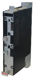
Номер модель:
8EI013HWSS0.XXXX-1Описание:
ACOPOS P3 servo drive, 3x 200-480 VAC, 13 A, SafeMOTION, 1 axis, wall mounting
Дополнительные аксессуары
Display modules
| 8EAD0000.000-1 | Display module, LCD, 128 x 64, black/white, 1x USB 3.0 |
Fan modules
| 8EXF100.0000-00 | ACOPOS P3 fan module, replacement fan for ACOPOS P3 servo drive single-width (8EI1X6/8EI2X2/8EI4X5/ 8EI8X8/8EI013/8EI017xxS) |
Front covers
| 8EXA200.0010-00 | ACOPOS P3 dover, B&R orange, single-width, suitable for servo drives 8EI2X2xxDxx.xxxx-x / 8EI2X2xxTxx.xxxx-x / 8EI4X5xxDxx.xxxx-x / 8EI4X5xxTxx.xxxx-x /8EI8X8xxDxx.xxxx-x / 8EI8X8xxTxx.xxxx-x / 8EI013xxSxx.xxxx-x / 8EI017xxSxx.xxxx-x |
| 8EXA200.0020-00 | ACOPOS P3 cover, B&R dark gray, single-width, suitable for servo drives 8EI2X2xxDxx.xxxx-x / 8EI2X2xxTxx.xxxx-x / 8EI4X5xxDxx.xxxx-x / 8EI4X5xxTxx.xxxx-x / 8EI8X8xxDxx.xxxx-x / 8EI8X8xxTxx.xxxx-x / 8EI013xxSxx.xxxx-x / 8EI017xxSxx.xxxx-x |
Line filters passive
| 8B0F0160H000.000-1 | Line filter, passive, 16 A, 3x 528 VAC, 50/60 Hz, IP20 |
| 8B0F0300H000.000-1 | Line filter, passive, 30 A, 3x 520 VAC, 50/60 Hz, IP20 |
| 8B0F0550H000.000-1 | Line filter, passive, 55 A, 3x 520 VAC, 50/60 Hz, IP20 |
Plug-in modules
| 8EAC0122.001-1 | ACOPOS P3 plug-in module, resolver interface 10 kHz |
| 8EAC0130.000-1 | ACOPOS P3 plug-in module, 8 digital I/O 24 V (4x 400 mA, 4x 100 mA) individually configurable as inputs or outputs, 2 digital I/O 24 V 2 A configurable in pairs as inputs or outputs, order terminal block 8TB0230.221A-00 separately! |
| 8EAC0150.001-1 | ACOPOS P3 plug-in module, digital multi-encoder interface |
| 8EAC0151.001-1 | ACOPOS P3 plug-in module, incremental encoder interface |
| 8EAC0152.001-1 | ACOPOS P3 plug-in module, analog multi-encoder interface |
Shield component sets
| 8SCSE01.0100-00 | ACOPOS P3 shield component set: 1x ACOPOS P3 shield mounting plate, 1x 2x M3x6 screws |
| 8SCSE02.0100-00 | ACOPOS P3 shield component set: 1x shield connection clamp type SK14 |
| 8SCSE02.0200-00 | ACOPOS P3 shield component set: 1x shield connection clamp type SK20 |
Terminal blocks
| 8TB2104.2210-00 | 4-pin push-in terminal block, 1-row, pitch: 5.08 mm, label 1: Numbered consecutively |
| 8TB3102.222C-20 | 2-pin push-in terminal block, 1-row, with locking mechanism, pitch: 7.62 mm, label 2: COM 24 V, coding C: 10 |
| 8TB3103.222A-20 | 3-pin push-in terminal block, 1-row, with locking mechanism, pitch: 7.62 mm, label 2: PE RB- RB+, coding A: 000 |
| 8TB3106.222B-20 | 6-pin push-in terminal block, 1-row, with locking mechanism, pitch: 7.62 mm, label 2: PE L3 L2 L1 DC- DC+, coding B: 000001 |
| 8TB3202.222C-40 | 2-pin push-in terminal block, 2-row, with locking mechanism, pitch: 7.62 mm, label 2: COM 24 V, coding C: 10 |
| 8TB3206.222B-40 | 6-pin push-in terminal block, 2-row, with locking mechanism, pitch: 7.62 mm, label 2: PE L3 L2 L1 DC- DC+, coding B: 000001 |
| 8TB3308.222A-00 | 4+4-pin push-in terminal block 1-row / 2-row, pitch: 7.62 mm, label 2: T- B- T+ B+ PE W V U coding A: 0000 |
Terminal set
| 8EZI8X8HSS.2201-0 | Terminal block set for ACOPOS P3 modules 8EI1X6H*SS, 8EI2X2H*SS, 8EI4X5H*SS, 8EI8X8H*SS, 8EI013H*SS, 8EI017H*SS: 1x 8TB2104.2210-00, 1x 8TB3102.222C-20, 1x 8TB3308.222A-00, 1x 8TB3106.222B-20, 1x 8TB3103.222A-20 |
| 8EZI8X8HSS.2202-0 | Terminal block set for ACOPOS P3 modules 8EI*X*H*SS0.****-1, 8EI01*H*SS0.****-1: 1x 8TB2104.2210-00, 1x 8TB3202.222C-40, 1x 8TB3308.222A-00, 1x 8TB3206.222B-40, 1x 8TB3103.222A-20 |
| E-CAD (Electro или EPLAN шаблоны) | Версия (Дата) | Загрузка |
|---|---|---|
| ACOPOSp3 EPLAN P8 from V2.4 | EXE / 183 МБ |
| M-CAD (Механические Шаблоны | Версия (Дата) | Загрузка |
|---|---|---|
| 3D STEP file 8EI01xxWSSx.xxxx-1 1-axis modules | ZIP / 989 кБ | |
| 3D STEP file 8EI01xxWSSx.xxxx-1 1-axis modules with 8EXA200 front cover | ZIP / 1 МБ |
| Документация | Версия (Дата) | Загрузка |
|---|---|---|
| Datasheet 8EI013HWSS0.XXXX-1 | PDF / 1 МБ | |
| Integrated safety technology user's manual | PDF / 59 МБ | |
| SafeMOTION User´s Manual | PDF / 34 МБ |
| Обновление Automation Studio HW | Версия (Дата) | Загрузка |
|---|---|---|
| V4.0 HW Upgrade (8EI013HWSS0.xxxx-1) | EXE / 243 кБ | |
| V4.2 HW Upgrade (8ESMC59314) | EXE / 765 кБ | |
| V4.4 HW Upgrade (8EI013HWSS0.xxxx-1) | EXE / 550 кБ | |
| V4.6 HW Upgrade (8ESMC59314) | EXE / 1 МБ | |
| V6.0 HW Upgrade (8EI013HWSS0.xxxx-1) | EXE / 273 кБ | |
| V6.0 HW Upgrade (8ESMC59314) | EXE / 1 МБ |