Short description
| I/O module | 4 inputs for thermocouple sensors |
General information
| Diagnostics | |
| Inputs | Yes, using LED status indicator and software |
| I/O power supply | Yes, using LED status indicator and software |
| Connection type | |
| X2X Link | M12, B-coded |
| Inputs | 4x M12, A-coded |
| I/O power supply | M8, 4-pin |
| Power consumption | |
| Internal I/O | 2.6 W |
| X2X Link power supply | 0.75 W |
| Certifications | |
| CE | Yes |
| UKCA | Yes |
| CRA (Cyber Resilience Act) | In preparation |
| ATEX |
Zone 2, II 3G Ex nA IIA T5 Gc IP67, Ta = 0 - Max. 60°C TÜV 05 ATEX 7201X |
| UL |
cULus E115267 Industrial control equipment |
| HazLoc |
cCSAus 244665 Process control equipment for hazardous locations Class I, Division 2, Groups ABCD, T5 |
| KC | Yes |
| B&R ID code | 0x1486 |
| Status indicators | I/O function per channel, supply voltage, bus function |
I/O power supply
| Nominal voltage | 24 VDC |
| Voltage range | 18 to 30 VDC |
| Integrated protective function | Reverse polarity protection |
Thermocouple temperature inputs
Electrical properties
| Electrical isolation |
Channel isolated from bus Channel not isolated from channel
|
Operating conditions
| Mounting orientation | |
| Any | Yes |
| Installation elevation above sea level | |
| 0 to 2000 m | No limitation |
| >2000 m | Reduction of ambient temperature by 0.5°C per 100 m |
| Degree of protection per EN 60529 | IP67 |
Ambient conditions
| Temperature | |
| Operation | -25 to 60°C |
| Derating | - |
| Storage | -40 to 85°C |
| Transport | -40 to 85°C |
Mechanical properties
| Dimensions | |
| Width | 53 mm |
| Height | 85 mm |
| Depth | 42 mm |
| Torque for connections | |
| M8 | Max. 0.4 Nm |
| M12 | Max. 0.6 Nm |
| Weight | 205 g |
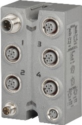
Número de material:
X67AT1402Descripción:
- 4 inputs for thermocouple sensors
- Sensor types J, K, N, R and S
- Additional direct raw value measurement for other sensor types
- Terminal temperature compensation
The module is a temperature module for type J, K, N, R and S thermocouple sensors. The selected sensor type is used for all 4 inputs.
| Actualizaciones de hardware de Automation Studio | Versión (fecha) | Descargar |
|---|---|---|
| V2.6 HW Upgrade (X67AT1402) | EXE / 2 MB | |
| V3.0 HW Upgrade (X67AT1402) | EXE / 2 MB | |
| V4.0 HW Upgrade (X67AT1402) | EXE / 1 MB |
| Documentación | Versión (fecha) | Descargar |
|---|---|---|
| Data sheet X67AT1402 | PDF / 971 KB | |
| X67 System User´s Manual | PDF / 19 MB |
| E-CAD (plantillas Electro o EPLAN) | Versión (fecha) | Descargar |
|---|---|---|
| X67 EPLAN P8 from V2.4 | EXE / 105 MB |
| M-CAD (plantillas mecánicas) | Versión (fecha) | Descargar |
|---|---|---|
| 3D File DXF/STEP X67 | ZIP / 2 MB |