Short description
| Inverter module | Connection for two servo motors with SSI absolute encoder |
General information
| Diagnostics | |
| Module run/error | Yes, using LED status indicator and software |
| Module temperature / Cooling unit temperature | Yes, using software |
| Motor status | Yes, using LED status indicator and software |
| POWERLINK | Yes, using LED status indicator |
| Electrical isolation | |
| CPU - 24 VDC power supply | No |
| CPU - Power supply | Yes |
| CPU - Motor connection | Yes |
| CPU - Digital inputs | Yes |
| CPU - Trigger inputs | Yes |
| CPU - Enable inputs | Yes |
| CPU - Encoder | No |
| CPU - Motor holding brake | No |
| CPU - POWERLINK | Yes |
| Certifications | |
| CE | Yes |
| UKCA | Yes |
| CRA (Cyber Resilience Act) | In preparation |
| UL |
cULus E225616 Power conversion equipment |
| B&R ID code | 0xE4DC |
| Status indicators | POWERLINK, operating state, module status, motor information |
Power supply
Motor connection
Motor holding brake connection
| Can be used for | |
| Axis 1 | Yes |
| Axis 2 | No |
| Switching frequency | |
| Resistive load | 100 Hz |
| Inductive load | See section "Switching inductive loads". |
| Protective measures | |
| Overload and short-circuit protection | Yes |
| Open-circuit monitoring | Yes |
| Undervoltage monitoring | Yes |
| Quantity | 1 |
| Nominal voltage | 24 VDC |
| Continuous current per connection | 1 A |
| Max. internal resistance | 0.3 Ω |
| Response threshold for open-circuit monitoring | <100 mA |
| Response threshold for undervoltage monitoring | ≤23.5 V |
Interfaces
| POWERLINK | |
| Variant | Female RJ45 connector |
| Electrical isolation | Yes |
Encoder inputs
| Encoder power supply | |
| Output voltage | 5 V ±5% |
| Load capacity | 250 mA |
| Synchronous serial interface | |
| Signal transmission | RS485 |
| Data transfer rate | Configurable (100 to 400 kbit/s) |
| Quantity | 2 |
| Type | SSI absolute encoder |
| Max. encoder cable length | 25 m |
Enable inputs
| Switching threshold | |
| Low | <5 VDC |
| High | >15 VDC |
| Switching delay at nominal input voltage | |
| Enable 1 → 0, PWM off | |
| Maximum | 500 ms (Rev. < E0: 551 ms) |
| Enable 0 → 1, ready for PWM | |
| Maximum | 500 ms |
| Quantity | 1 |
| Nominal voltage | 24 VDC |
| Input voltage | 24 VDC ±25% |
| Input current at nominal voltage | Typ. 60 mA |
| Input circuit | Sink |
| Insulation voltage between input and bus | 500 Veff |
| Input capacitance | 10 nF (Rev. < E0: 100 µF) |
Digital inputs / Trigger inputs
| Input voltage | |
| Nominal | 24 VDC |
| Maximum | 30 VDC |
| Switching threshold | |
| Low | <5 VDC |
| High | >15 VDC |
| Switching delay | |
| Rising edge | [Instant recording] Typ. 52 µs |
| Falling edge | [Instant recording] Typ. 53 µs |
| Electrical isolation | |
| Input - ACOPOS | Yes, 500 Veff |
| Input - Input | Yes, 500 Veff |
| Quantity | 2 |
| Additional functions | Can be used as trigger input |
| Input circuit | Sink |
| Input current at nominal voltage | Approx. 7.5 mA |
| Input resistance | Approx. 3.2 kΩ |
| Modulation compared to ground potential | Max. ±38 V |
Operating conditions
| Mounting orientation | |
| Horizontal | No |
| Vertical | Yes |
| Pollution degree per EN 61800-5-1 | 2 (non-conductive pollution) |
| Degree of protection per EN 60529 | IP20 |
Ambient conditions
| Temperature | |
| Operation | 0 to 45°C |
| Storage | -25 to 55°C |
| Transport | -25 to 55°C |
| Relative humidity | |
| Operation | 5 to 85%, non-condensing |
| Storage | 5 to 95%, non-condensing |
| Transport | 5 to 95%, non-condensing |
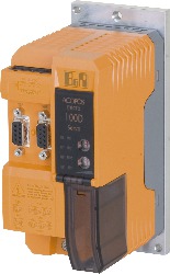
Material number:
80VD100PD.C033-01Description:
- Control for 2 servo motors
- 2 SSI absolute encoder interface
- 2 trigger inputs
- Connection for motor holding brake
- Enable input
Mandatory Accessories
Terminal block sets
| 80XVD100PD.C0-01B | Cage clamp terminal block set for ACOPOSmicro modules 80VD100PD.xxxx-01: 1x 0TB1110.8110-1, 1x 0TB2105.9121-01, 1x 0TB2104.4121-01, 1x 0TB2104.4122-01, 1x 0TB2102.4121-01, 1x 0TB2102.4122-01 |
| 80XVD100PD.C0-01A | Screw clamp terminal block set for ACOPOSmicro modules 80VD100PD.xxxx-01: 1x 0TB1110.8010, 1x 0TB2105.9021, 1x 0TB2104.4021, 1x 0TB2104.4022, 1x 0TB2102.4021, 1x 0TB2102.4022 |
Optional Accessories
Braking resistor
| 80XBR0055.010-11 | Braking resistor for ACOPOSmicro 5.5 Ω 100 W |
Hose clamps
| 80XSC0000.00-10 | Accessory for ACOPOSmicro: 10x hose clamp, B 9 mm, D 8-12 mm |
| 80XSC0000.00-01 | Accessory for ACOPOSmicro: 1x hose clamp, B 9 mm, D 8-12 mm |
Terminal blocks
| 0TB1310.8110 | Accessory terminal block, 3x 10-pin, cage clamp terminal block 1.5 mm², protected against vibration by the screw flange, with labeling |
| 0TB1310.3100 | Accessory terminal block, 3x 10-pin, cage clamp terminal block, 1.5 mm², protected against vibration by the screw flange |
| Automation Studio HW Upgrades | Version (Date) | Download |
|---|---|---|
| V3.0 HW Upgrade (80VD100PD.C033-01) | EXE / 24 MB | |
| V4.0 HW Upgrade (80VD100PD.C033-01) | EXE / 719 KB |
| Documentation | Version (Date) | Download |
|---|---|---|
| ACOPOSmicro User's Manual | PDF / 68 MB |
| E-CAD (Electro or EPLAN Templates) | Version (Date) | Download |
|---|---|---|
| ACOPOSmicro EPLAN P8 | EXE / 13 MB |
| M-CAD (Mechan. Templates) | Version (Date) | Download |
|---|---|---|
| 3D file DXF/STEP ACOPOSmicro Servo | ZIP / 15 MB |