Short description
Bus controller CANopen
General information
Insulation voltage for GND and housing 500 Veff
B&R ID code 0xF23F
Cooling Fanless
Status indicators No
Diagnostics
Module run/error Yes, using software
Controller function Yes, using software
Power consumption With active 5 V sensor power supply: 3 to 3.3 W
With active 10 V sensor power supply: 6.1 to 9 W
Certifications
UN ECE-R10 Yes
CE Yes
UKCA Yes
Input power supply
Input voltage 9 to 32 VDC
Controller
Real-time clock No
FPU Yes
Processor
Type ARM Cortex-M4
Integrated I/O processor Processes I/O data points in the background
Option boards 0
Interfaces
CAN
Variant Connection on CMC header X1
Transfer rate Max. 1 Mbit/s
Max. distance 1000 m
Terminating resistor External 120 Ω must be provided.
Multi-function inputs
Multifunction digital inputs (MF-DI)
Quantity 4
Functions Digital input
Sink/Source circuit, configurable software input filter, fixed or ratiometrically configurable threshold value, open-circuit and short-circuit detection.
Counter function
Input frequency max. 50 kHz, period duration or gate measurement, AB/ABR encoder, DF/edge counter, rising or falling edge
Analog input
Measurement range 0 to 32 V, configurable analog filter, configurable limit values, integrated input protection
Multifunction analog inputs (MF-AI)
Quantity 12
Functions Analog input
MF-AI-T
Measurement ranges 0 to 10 V / 0 to 32 V / 0 to 20 mA / 4 to 20 mA / 0 to 4 kΩ / -80 to 270°C, configurable analog filter, configurable limit values, integrated input protection
MF-AI-1
Measurement ranges 0 to 10 V / 0 to 32 V / 0 to 20 mA / 4 to 20 mA, configurable analog filter, configurable limit values, integrated input protection
MF-AI-2
Measurement ranges 0 to 10 V / 0 to 32 V, configurable analog filter, configurable limit values, integrated input protection
LED driver
Max. 20 mA
Digital input
Sink/Source circuit, configurable software input filter, fixed or ratiometrically configurable threshold value, open-circuit and short-circuit detection.
Multi-function outputs
Multifunction digital outputs (MF-DO)
Quantity 4
Functions Digital output
4 A nominal current, 2 channels source circuit, 2 channels sink circuit, integrated output protection, parallel connection of source channels possible.
Digital input
Sink circuit, configurable software input filter, fixed configurable threshold value, open-circuit and short-circuit detection.
Analog input
Measurement range 0 to 32 V, configurable analog filter, configurable limit values, integrated input protection
Multifunction PWM outputs (MF-PWM)
Quantity 8
Functions Digital output
4 A nominal current, source circuit, integrated output protection, parallel connection possible.
PWM output
4 A nominal current, PWM frequency 15 Hz to 1 kHz, current control function, integrated output protection, parallel connection possible, configurable switch-on/switch-off ramp, dither
Digital input
Sink circuit, configurable software input filter, fixed or ratiometrically configurable threshold value, open-circuit and short-circuit detection.
Analog input
Measurement range 0 to 32 V, configurable analog filter, configurable limit values, integrated input protection
Multifunction PVG outputs (MF-PVG)
Quantity 4
Functions Digital output
10 mA nominal current at 24 V, sink/source circuit, integrated output protection.
PVG output
10 mA nominal current at 24 V, PVG frequency 15 Hz to 1 kHz.
Digital input
Sink/Source circuit, configurable software input filter, fixed configurable threshold value, open-circuit and short-circuit detection.
Analog input
Measurement range 0 to 32 V, configurable analog filter, configurable limit values, integrated input protection
CPU/Controller power supply
Voltage range 9 to 32 VDC
Input current Max. 3 A
Integrated protection No, required fuse max. 3 A slow-blow
I/O power supply
Voltage range 9 to 32 VDC
Input current Max. 10 A per pin
Integrated protection No, required fuse max. 10 A slow-blow
Digital inputs
Quantity 0 to 32, depends on the use of multifunction inputs/outputs
Nominal voltage 12 / 24 VDC
Input voltage 9 to 32 VDC
Input current at 24 VDC MF-DI: 1.2 mA
MF-AI: 1.2 mA
MF-DO_plus: <1 mA
MF-PWM: <1 mA
MF-PVG: Typ. 10 mA
Input circuit Sink/Source, configurable
Input filter
Hardware MF-DI: 3 μs if switching threshold = 50% supply voltage
MF-AI: 600 μs if switching threshold = 50% supply voltage
MF-DO: 300 μs
MF-PWM: 150 μs
Software Default 1 ms, configurable between 0 and 25 ms in 0.1 ms increments
Input resistance MF-AI and MF-DI: Typ. 22 kΩ
Additional functions Counter functions (inputs 13 to 16)
Edge detection: Max. 50 kHz
Period duration / Gate measurement: Max. 3.5 kHz
ABR, AB and DF counters
Input frequency MF-DI: Max. 50 kHz
Switching threshold MF-DI: 50% of supply voltage
MF-AI: Switching threshold and hysteresis configurable with software
MF-DO: 50% supply voltage
MF-PWM: 50% supply voltage
Analog inputs
Input 0 to 10 V / 0 to 32 V / 0 to 20 mA / 4 to 20 mA / 0 to 4 kΩ / -80 to 270°C
Digital converter resolution 12-bit
Conversion time 250 μs
Output format
Data type INT, UINT (resistance)
Voltage Voltage 0 to 10 V: INT 0x0000 - 0x7FFF / 1 LSB = 0x0008 = 2.44 mV
Voltage 0 to 32 V: INT 0x0000 - 0x7FFF / 1 LSB = 0x0008 = 7.81 mV
Current INT 0x0000 - 0x7FFF / 1 LSB = 0x0008 = 4.9 μA
Resistance 0 to 4000, 1 Ω increments
Temperature input -80 to 270, 0.1°C increments
Input impedance in signal range
Voltage >100 kΩ
Current -
Measurement current resistance / Temperature input <1.2 mA
Load
Voltage -
Current <300 Ω
Open-circuit detection From the application
Reverse polarity protection Yes
Conversion procedure SAR
Input filter Low-pass filter / Cutoff frequency voltage input / Current input 200 Hz
Max. error
Voltage
Gain <1%
Offset <1%
Current
Gain <1%
Offset <1%
Resistance <1%
Temperature input <1%
Max. gain drift
Voltage <0.03%/°C
Current <0.04%/°C
Resistance 0.034%
Temperature input 0.024%
Max. offset drift
Voltage <0.006%/°C
Current <0.02%/°C
Resistance 0.0018%/°C
Temperature input 0.027%/°C
Sensor power supply
Voltage 5 / 10 V
Current Maximum 400 mA, accuracy: ±4%
Digital outputs
Quantity 0 to 23, depends on the use of multifunction outputs
Variant 7x MF-AI, LED driver: Current-sinking
2x MF-DO_minus: Current-sinking
2x MF-DO_plus: Current-sourcing, channels can be connected in parallel (max. 6.5 A).
8x MF-PWM: Current-sourcing, channels can be connected in parallel.
4x MF-PVG: Current-sourcing/Current-sinking
Nominal voltage 12 / 24 VDC
Digital converter resolution 12-bit
Output format MF-AI LED driver: INT 0x0000 to 0x7FFF / 1 LSB = 0x0008 = 4.9 µA
MF-DO_plus: INT 0x0000 to 0x7FFF / 1 LSB = 0x0008 = 1.22 mA
MF-DO_minus: INT 0x0000 to 0x7FFF / 1 LSB = 0x0008 = 2.21 mA
MF-PWM: INT 0x0000 to 0x7FFF / 1 LSB = 0x0008 = 1.22 mA
MF-PVG: INT 0x0000 to 0x7FFF / 1 LSB = 0x0008 = 7.81 mV
Nominal output current MF-AI LED driver: 20 mA
MF-DO: 4 A
MF-PWM: 4 A
MF-PVG: 10 mA
Output protection Shutdown in the event of overcurrent or short circuit, integrated protection for switching inductive loads
Diagnostic status Overload
Leakage current when the output is switched off MF-AI LED driver: 10 µA
MF-DO: 10 μA
MF-PWM: 10 μA
MF-PVG: 10 µA
RDS(on) MF-AI LED driver: 2 Ω
MF-DO_minus: 70 mΩ
MF-DO_plus: 50 mΩ
MF-PWM: 50 mΩ
MF-PVG: 2 Ω
Residual voltage <1 V at 4 A nominal current
Peak short-circuit current MF-AI LED driver: 20 mA
MF-DO_minus: Max. 24 A
MF-DO_plus: Max. 90 A
MF-PWM: Max. 90 A
MF-PVG: Max. 10 mA
Switching frequency
Resistive load MF-AI LED driver: Max. 100 Hz
MF-DO: Max. 100 Hz
MF-PWM: 15 Hz to 1 kHz
MF-PVG: 15 Hz to 1 kHz
Max. error at 25°C
Gain MF-AI LED driver: <1%
MF-DO: <12%
MF-PWM: <0.2%
MF-PVG: <5%
Offset MF-AI LED driver: <1%
MF-DO: <1%
MF-PWM: <0.1%
MF-PVG: <1%
Max. gain drift MF-DO: <0.2%/°C
MF-PWM: <0.04%/°C
Max. offset drift MF-DO: <0.005%/°C
MF-PWM: <0.005%/°C
Braking voltage when switching off inductive loads MF-DO: Typ. 64 VDC
Switching delay MF-DO: Max. 2 ms
Output voltage
Nominal 9 to 32 VDC
Current measurement
Current measurement range MF-AI LED driver: 0 to 20 mA
MF-DO_plus: 0 to 20 A
MF-DO_minus: 0 to 5 A
MF-PWM: 0 to 5 A
Sampling frequency MF-AI LED driver: 250 µs
MF-DO: 250 μs
MF-PWM: 50 μs
MF-PVG: 250 µs
PWM output
Quantity 0 to 8x 4 A
Depends on the use of multifunction outputs
Nominal voltage 12 / 24 VDC
Supply voltage (permissible range) 9 to 32 VDC
Digital converter resolution 12-bit
Output format MF-PWM: INT 0x0000 to 0x7FFF / 1 LSB = 0x0008 = 1.22 mA
PWM frequency 15 Hz to 1 kHz
Duty cycle 0 to 32767, equivalent 0 to 100%
Max. error at 25°C
Gain <0.2%
Offset <0.1%
Max. gain drift <0.04%/°C
Max. offset drift <0.005%/°C
Common mode error 0.015%/V
Output protection Thermal shutdown in the event of overcurrent or short circuit, integrated protection for switching inductive loads
Variant Current-sourcing FET, channels can be connected in parallel in pairs.
Diagnostic status Overload
Peak short-circuit current 90 A
Current measurement
Current measurement range 0 to 5 A
Conversion time 250 μs
Electrical properties
Summation current
Complete system Max. 25.5 A
Operating conditions
Mounting orientation
Any Yes
Degree of protection IP69K
Ambient conditions
Temperature
Operation -40 to 85°C housing surface
Derating -
Storage -40 to 85°C
Transport -40 to 85°C
Relative humidity
Operation 5 to 100%, condensing
Storage 5 to 95%, non-condensing
Transport 5 to 95%, non-condensing
Mechanical properties
Dimensions
Width 153 mm
Length 140 mm
Height 44 mm
Weight 700 g
Material number:
X90BC124.32-00
Description:
  • Agricultural and forestry machines
  • Construction machinery
  • Municipal utility vehicles
  • Stationary outdoor applications
  • 32 multifunction inputs or outputs
  • Sensor power supply
  • CANopen connection (daisy chain)

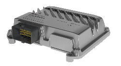
Bus controller module X90BC124.32-00 is a configurable CANopen slave module for sensor and actuator management. 32 multifunction inputs and outputs are available for a wide range of tasks.

The robust die-cast aluminum housing enables use in harsh ambient conditions.

Optional Accessories
BreakOut Box
X90AC-BB.12-00 X90 mobile 120, breakout box template and cable adapter for X90AC-BB.17-00 breakout box, for development and tests
CMC connector
X90TB120.01-00 X90 mobile 120, connector set for CMC header, with connector contacts and dummy plugs
Wire harness
X90CA124.02-00 X90 mobile 120, wiring harness starter set for X90BC124, 2 m, for CMC header
Automation Studio HW Upgrades Version (Date) Download
V4.7 HW Upgrade (X90BC124.32-00) EXE / 4 MB
Certificates Version (Date) Download
EU Declaration Industrial sector X90 PDF / 163 KB
EU Declaration Mobile machinery X90 PDF / 146 KB
EU Declaration Railway X90 PDF / 224 KB
UK Declaration Industrial sector X90 PDF / 110 KB
UN ECE-R10 (X90BC124) PDF / 137 KB
Documentation Version (Date) Download
Data sheet X90BC124.32-00 PDF / 3 MB
X90 BC pin allocation CMC connector ZIP / 1 MB
X90 mobile System User´s Manual PDF / 45 MB
E-CAD (Electro or EPLAN Templates) Version (Date) Download
Makro-/Artikeldaten 4.0.2 (X90BC124.32-00) EXE / 3 MB
X90 EPLAN P8 from V2.4 EXE / 69 MB
M-CAD (Mechan. Templates) Version (Date) Download
3D files DXF/STEP X90BC124.32-00 ZIP / 4 MB

Please choose country and language

B&R Logo