Short description
| I/O module |
2 SSI absolute encoders 5 V or 2 ABR incremental encoders 5 V, 4 AB counters or 4 up/down counters 24 V, 2x pulse width modulation, time measurement, relative timestamp |
General information
| Insulation voltage between encoder and bus | 500 Veff |
| B&R ID code | 0x18D0 |
| Sensor/Actuator power supply | 0.5 A summation current |
| Status indicators | I/O function per channel, supply voltage, bus function |
| Diagnostics | |
| Outputs | Yes, using LED status indicator and software |
| I/O power supply | Yes, using LED status indicator and software |
| Connection type | |
| X2X Link | M12, B-coded |
| Inputs/Outputs | 2x M12, 5-pin, A-coded |
| SSI/ABR encoder | 2x M12, 12-pin, A-coded |
| I/O power supply | M8, 4-pin |
| Power consumption | |
| Internal I/O | 2.8 W |
| X2X Link power supply | 0.75 W |
| Certifications | |
| CE | Yes |
| UKCA | Yes |
| CRA (Cyber Resilience Act) | In preparation |
| ATEX |
Zone 2, II 3G Ex nA IIA T5 Gc IP67, Ta = 0 - Max. 60°C TÜV 05 ATEX 7201X |
| UL |
cULus E115267 Industrial control equipment |
| HazLoc |
cCSAus 244665 Process control equipment for hazardous locations Class I, Division 2, Groups ABCD, T5 |
| KC | Yes |
I/O power supply
Sensor/Actuator power supply
| Voltage | I/O power supply minus voltage drop for short-circuit protection |
| Voltage drop for short-circuit protection at 0.5 A | Max. 2 VDC |
| Summation current | Max. 0.5 A |
| Short-circuit proof | Yes |
SSI absolute encoder
| Quantity | 2 |
| Encoder inputs | 5 V, symmetrical |
| Counter size | 32-bit |
| Max. transfer rate | 1 Mbit/s |
| Coding | Gray/Binary |
| Overload characteristics of encoder power supply | Short-circuit proof, overload-proof |
| Transfer rate | 125 kbit/s, 250 kbit/s, 500 kbit/s, 1 Mbit/s |
| Encoder power supply | |
| 5 VDC | Module-internal, max. 0.3 A summation current |
| 24 VDC | Module-internal, max. 0.5 A summation current |
ABR incremental encoder
| Quantity | 2 |
| Encoder inputs | 5 V, symmetrical |
| Counter size | 16/32-bit |
| Input frequency | Max. 250 kHz |
| Evaluation | 4x |
| Encoder power supply | |
| 5 VDC | Module-internal, max. 0.3 A summation current |
| 24 VDC | Module-internal, max. 0.5 A summation current |
| Input filter | |
| Hardware | ≤200 ns |
| Software | - |
| Common-mode range | -7 V ≤ VCM ≤ +12 V |
| Overload characteristics of encoder power supply | Short-circuit proof, overload-proof |
AB counters
| Quantity | 4 |
| Evaluation | 4x |
| Input frequency | Max. 100 kHz |
| Encoder inputs | 24 V, asymmetrical |
| Encoder power supply 24 VDC | Module-internal, max. 0.5 A summation current |
| Counter size | 16/32-bit |
Digital inputs 5 VDC
| Quantity | Up to 6, configuration as input or output using software |
| Nominal voltage | 5 VDC differential signal, EiA RS485 standard |
| Input characteristics per EN 61131-2 | Type 1 |
| Input filter | |
| Hardware | 200 ns |
| Software | - |
| Additional functions | ABR incremental encoder, SSI absolute encoder, event counting, time measurement, relative timestamp |
Digital inputs 24 VDC
| Quantity | Up to 8, configuration as input or output using software |
| Nominal voltage | 24 VDC |
| Input characteristics per EN 61131-2 | Type 1 |
| Input circuit | Sink |
| Input voltage | 18 to 30 VDC |
| Input filter | |
| Hardware | ≤2 µs |
| Software | - |
| Input current at 24 VDC | Approx. 3.3 mA |
| Input resistance | 7.31 kΩ |
| Switching threshold | |
| Low | <5 VDC |
| High | >15 VDC |
| Additional functions | Reference enable inputs for ABR, event counting, latch function, time measurement, relative timestamp |
Event counters
| Quantity | 8 |
| Evaluation | 2x |
| Input frequency | Max. 100 kHz |
| Encoder inputs | 24 V, asymmetrical |
| Encoder power supply 24 VDC | Module-internal, max. 0.5 A summation current |
| Counter size | 16/32-bit |
Up/Down counters
| Quantity | 4 |
| Evaluation | 2x |
| Input frequency | Max. 100 kHz |
| Encoder inputs | 24 V, asymmetrical |
| Encoder power supply 24 VDC | Module-internal, max. 0.5 A summation current |
| Counter size | 16/32-bit |
Edge detection / Time measurement
| Possible measurements | Gate time, period duration, edge offset for various channels |
| Measurements per module | Up to 9 |
| Measurements per channel | Up to 2 |
| Signal form | Square wave pulse |
| Counter size | 16-bit |
| Counter frequency | |
| Internal | 8 MHz, 4 MHz, 2 MHz, 1 MHz, 500 kHz, 250 kHz, 125 kHz, 62.5 kHz |
| Measurement type | Continuous or triggered |
Digital outputs 5 VDC
| Quantity | Up to 6, configuration as input or output using software |
| Type | 5 VDC differential signal, EiA RS485 standard |
| Output circuit | Sink or source |
| Output protection | Short circuit protection |
| Variant | Push / Pull / Push-Pull |
| Diagnostic status | Output monitoring |
Digital outputs 24 VDC
Electrical properties
| Electrical isolation |
Bus isolated from encoder and channel Channel not isolated from channel and encoder Encoder not isolated from encoder
|
Operating conditions
| Mounting orientation | |
| Any | Yes |
| Installation elevation above sea level | |
| 0 to 2000 m | No limitation |
| >2000 m | Reduction of ambient temperature by 0.5°C per 100 m |
| Degree of protection per EN 60529 | IP67 |
Ambient conditions
| Temperature | |
| Operation | -25 to 60°C |
| Derating | - |
| Storage | -40 to 85°C |
| Transport | -40 to 85°C |
Mechanical properties
| Dimensions | |
| Width | 53 mm |
| Height | 85 mm |
| Depth | 42 mm |
| Weight | 200 g |
| Torque for connections | |
| M8 | Max. 0.4 Nm |
| M12 | Max. 0.6 Nm |
物料号:
X67DC1198描述:
- 2 incremental or SSI encoder inputs 5 V
- 2 digital channels, 24 V per connection, configurable either as inputs or outputs
- 4 AB counters on the digital inputs
- Pulse width modulation of the digital outputs
- Encoder power supply 5 V and 24 V integrated in encoder connection
The possibilities are almost endless with this digital counter module.
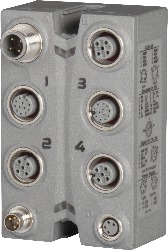
Connectors 1 and 3 are 12-pin M12 connectors. Each of these can be used to connect 1 incremental encoder or SSI encoder with 5 V differential signals. In addition, there are 2 digital channels available on the same output which, when configured as inputs, can be used with incremental encoders with status outputs (e.g. alarms). When configured as outputs, they act as preset and count direction switching functions when used together with SSI encoders, for example.
2 more sockets and 2 more configurable digital channels are available on female connectors 2 and 4. The inputs can be used as latch, gate, or home enable switches, while the outputs can be used as comparator outputs, for example.
| Automation Studio硬件升级 | 版本(日期) | 下载 |
|---|---|---|
| V2.6 HW Upgrade (X67DC1198) | EXE / 3 MB | |
| V3.0 HW Upgrade (X67DC1198) | EXE / 4 MB | |
| V4.0 HW Upgrade (X67DC1198) | EXE / 3 MB |
| E-CAD(电子或EPLAN模板) | 版本(日期) | 下载 |
|---|---|---|
| X67 EPLAN P8 from V2.4 | EXE / 105 MB |
| M-CAD(机械模板) | 版本(日期) | 下载 |
|---|---|---|
| 3D File DXF/STEP X67 | ZIP / 2 MB |
| 文档 | 版本(日期) | 下载 |
|---|---|---|
| Data sheet X67DC1198 | PDF / 2 MB | |
| X67 System User´s Manual | PDF / 19 MB |