Short description
| I/O module | 8 safe type A digital inputs, 4 pulse outputs, 24 VDC, 6 safe type B2 digital outputs, 24 VDC, 0.2 A, OSSD <10 µs |
General information
Safety characteristics
| Note | See section "Safety characteristics". |
I/O power supply
| Nominal voltage | 24 VDC |
| Voltage range | 24 VDC -15% / +20% |
| Integrated protective function | Reverse polarity protection |
Safe digital inputs
Safe digital HS-HS outputs
| Quantity | 6 |
| Variant | FET, 2x positive switching, type B2, output level readable |
| Nominal voltage | 24 VDC |
| Nominal output current | 0.2 A |
| Total nominal current | 1.2 A |
| Output protection | See section "Inrush current behavior for output channels". |
| Braking voltage when switching off inductive loads | Max. 45 VDC |
| Error detection time | 1 s |
| Insulation voltage between channel and bus | 500 Veff |
| Peak short-circuit current | See section "Inrush current behavior for output channels". |
| Leakage current when the output is switched off | <100 µA |
| RDS(on) | 5 Ω |
| Switching voltage | I/O power supply minus voltage drop due to RDS(on) |
| Max. switching frequency | See section "Inrush current behavior for output channels". |
| Test pulse length | Max. 10 µs |
| Max. capacitive load | 100 nF |
Current on loss of ground
| IOUT | <100 µA |
| IGND | <200 mA |
Pulse outputs
Operating conditions
| Mounting orientation | |
| Horizontal | Yes |
| Vertical | Yes |
| Installation elevation above sea level | 0 to 2000 m, no limitation |
| Degree of protection per EN 60529 | IP20 |
Ambient conditions
| Temperature | |
| Operation | |
| Horizontal mounting orientation | 0 to 60°C |
| Vertical mounting orientation | 0 to 50°C |
| Derating | See section "Derating". |
| Storage | -40 to 85°C |
| Transport | -40 to 85°C |
| Relative humidity | |
| Operation | 5 to 95%, non-condensing |
| Storage | 5 to 95%, non-condensing |
| Transport | 5 to 95%, non-condensing |
Mechanical properties
| Note |
Order 2x safety-keyed terminal block separately. Order 1x safety-keyed bus module separately. |
| Pitch | 25+0.2 mm |
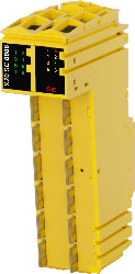
Malzeme numarası:
X20SC0806Açıklama:
- 8 safe digital inputs, sink circuit
- 4 pulse outputs
- Software input filter configurable for each channel
- 6 safe digital outputs, output type B with 0.2 A, source circuit
- Integrated output protection
The module is equipped with 8 safe digital inputs and 6 safe digital outputs. It is designed for a nominal voltage of 24 VDC.
The module can be used to read in digital signals and to control actuators in safety-related applications up to PL e or SIL 3.
The module is equipped with filters that are individually configurable for switch-on and switch-off behavior. The module also provides pulse signals for diagnosing the sensor line.
The outputs are designed using semiconductor technology so that the safety-related characteristics do not depend on the number of operating cycles. The "high-side high-side" variant (output type B) is required for actuators with reference potential (e.g. Enable inputs on frequency inverters). It is important to observe the special notices for the cabling in this case. Safe digital output channels provide protection against automatic restart when network errors occur.
This module is designed for X20 12-pin terminal blocks.
Zorunlu aksesuarlar
| Araçlar / Yardımcı Programlar / Örnekler | Sürüm (Tarih) | İndirme |
|---|---|---|
| Sistema (VDMA) library | ZIP / 5 KB |
| Automation Studio donanım yükseltmeleri | Sürüm (Tarih) | İndirme |
|---|---|---|
| V4.0 HW Upgrade (X20SC0806) | EXE / 4 MB | |
| V4.6 HW Upgrade (X20SC0806) | EXE / 2 MB | |
| V6.0 HW Upgrade (X20SC0806) | EXE / 494 KB |
| Dökümantasyon | Sürüm (Tarih) | İndirme |
|---|---|---|
| Data sheets SafeIO and SafeLogic | PDF / 29 MB | |
| Integrated safety technology user's manual | PDF / 59 MB | |
| X20 Package leaflet ATEX/CSA | PDF / 2 MB | |
| X20 System User´s Manual | PDF / 49 MB |
| E-CAD (Elektro veya EPLAN şablonları) | Sürüm (Tarih) | İndirme |
|---|---|---|
| X20 EPLAN P8 from V2.4 | EXE / 160 MB |
| M-CAD (Mechan. Şablonlar) | Sürüm (Tarih) | İndirme |
|---|---|---|
| 3D file STEP/DXF X20(c)Sxxxxx | ZIP / 1 MB |