Short description
| I/O module | 4 safe type A digital outputs, with current monitoring, 24 VDC, 0.5 A, OSSD <500 µs |
General information
Safety characteristics
| Note | See section "Safety characteristics". |
I/O power supply
| Nominal voltage | 24 VDC |
| Voltage range | 24 VDC -15% / +20% |
| Integrated protective function | Reverse polarity protection |
Safe digital outputs
Operating conditions
| Mounting orientation | |
| Horizontal | Yes |
| Vertical | Yes |
| Installation elevation above sea level | 0 to 2000 m, no limitation |
| Degree of protection per EN 60529 | IP20 |
Ambient conditions
| Temperature | |
| Operation | |
| Horizontal mounting orientation | 0 to 60°C |
| Vertical mounting orientation | 0 to 50°C |
| Derating | See section "Derating". |
| Storage | -40 to 85°C |
| Transport | -40 to 85°C |
| Relative humidity | |
| Operation | 5 to 95%, non-condensing |
| Storage | 5 to 95%, non-condensing |
| Transport | 5 to 95%, non-condensing |
Mechanical properties
| Note |
Order 1x safety-keyed terminal block separately. Order 1x safety-keyed bus module separately. |
| Pitch | 25+0.2 mm |
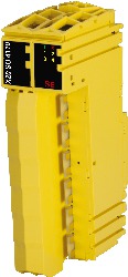
Materialnummer:
X20SO4110Beskrivning:
- 4 safe digital outputs with 0.5 A
- Source circuit
- Output type A
- Current monitoring
- Open circuit detection
- Integrated output protection
This module is equipped with 4 safe digital outputs. The nominal output current is 0.5 A.
The module can be used for controlling actuators in safety-related applications up to PL e or SIL 3.
The outputs are designed using semiconductor technology so that the safety-related characteristics do not depend on the number of operating cycles. The "high-side low-side" variant (output type A) is limited to actuators without reference potential (e.g. relays, valves). Type A outputs have safety-related advantages since the actuator can be cut off in its connection cable in all error scenarios. Safe digital output channels provide protection against automatic restart when network errors occur and also using a current measurement for open circuit detection.
This module is designed for X20 12-pin terminal blocks.
Obligatoriska tillbehör
| Automation Studio HW uppdateringar | Version (datum) | Ladda ner |
|---|---|---|
| V3.0 HW Upgrade (X20SO4110) | EXE / 1 MB | |
| V4.0 HW Upgrade (X20SO4110) | EXE / 2 MB | |
| V4.6 HW Upgrade (X20SO4110) | EXE / 2 MB | |
| V6.0 HW Upgrade (X20SO4110) | EXE / 473 KB |
| Dokumentation | Version (datum) | Ladda ner |
|---|---|---|
| Data sheets SafeIO and SafeLogic | PDF / 29 MB | |
| Integrated safety technology user's manual | PDF / 59 MB | |
| X20 Package leaflet ATEX/CSA | PDF / 2 MB | |
| X20 System User´s Manual | PDF / 49 MB |
| E-CAD (Electro eller EPLAN mallar) | Version (datum) | Ladda ner |
|---|---|---|
| X20 EPLAN P8 from V2.4 | EXE / 160 MB |
| M-CAD (Mechan. mallar) | Version (datum) | Ladda ner |
|---|---|---|
| 3D File STEP X20SO4110 | ZIP / 3 MB | |
| 3D file STEP X20(c)Sxxxxx - Terminal block right side | ZIP / 21 KB | |
| DFX File I/O Slice | ZIP / 4 KB | |
| Dimensions PDF X20 I/O Slice | PDF / 45 KB |
| Verktyg / Exempel | Version (datum) | Ladda ner |
|---|---|---|
| Sistema (VDMA) library | ZIP / 5 KB |