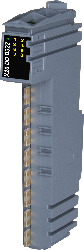
Short description
I/O module 8 digital outputs 24 VDC for 1- or 2-wire connections
General information
B&R ID code 0xC0E9
Status indicators I/O function per channel, operating state, module status
Diagnostics
Module run/error Yes, using LED status indicator and software
Outputs Yes, using LED status indicator and software (output error status)
Power consumption
Bus 0.19 W
Internal I/O 0.8 W
Additional power dissipation caused by actuators (resistive) [W] +0.28
Certifications
CE Yes
UKCA Yes
ATEX Zone 2, II 3G Ex nA nC IIA T5 Gc
IP20, Ta (see X20 user's manual)
FTZÚ 09 ATEX 0083X
UL cULus E115267
Industrial control equipment
HazLoc cCSAus 244665
Process control equipment
for hazardous locations
Class I, Division 2, Groups ABCD, T5
DNV Temperature: B (0 to 55°C)
Humidity: B (up to 100%)
Vibration: B (4 g)
EMC: B (bridge and open deck)
LR ENV1
KR Yes
ABS Yes
BV EC33B
Temperature: 5 - 55°C
Vibration: 4 g
EMC: Bridge and open deck
EAC Yes
KC Yes
Digital outputs
Variant Current-sourcing FET
Nominal voltage 24 VDC
Switching voltage 24 VDC -15% / +20%
Nominal output current 0.5 A
Total nominal current 4 A
Connection type 1- or 2-wire connections
Output circuit Source
Output protection Thermal shutdown in the event of overcurrent or short circuit (see value "Short-circuit peak current")
Internal freewheeling diode for switching inductive loads (see section "Switching inductive loads")
Diagnostic status Output monitoring with 10 ms delay
Leakage current when the output is switched off 5 µA
RDS(on) 140 mΩ
Peak short-circuit current <3 A
Switch-on in the event of overload shutdown or short-circuit shutdown Approx. 10 ms (depends on the module temperature)
Switching delay
0 → 1 <300 µs
1 → 0 <300 µs
Switching frequency
Resistive load Max. 500 Hz
Inductive load See section "Switching inductive loads".
Braking voltage when switching off inductive loads Typ. 45 VDC
Insulation voltage between channel and bus 500 Veff
Electrical properties
Electrical isolation Channel isolated from bus
Channel not isolated from channel and I/O power supply
Operating conditions
Mounting orientation
Horizontal Yes
Vertical Yes
Installation elevation above sea level
0 to 2000 m No limitation
>2000 m Reduction of ambient temperature by 0.5°C per 100 m
Degree of protection per EN 60529 IP20
Ambient conditions
Temperature
Operation
Horizontal mounting orientation -25 to 60°C
Vertical mounting orientation -25 to 50°C
Derating -
Storage -40 to 85°C
Transport -40 to 85°C
Relative humidity
Operation 5 to 95%, non-condensing
Storage 5 to 95%, non-condensing
Transport 5 to 95%, non-condensing
Mechanical properties
Note Order 1x terminal block X20TB1F separately.
Order 1x bus module X20BM11 separately.
Pitch 12.5+0.2 mm
Materialnummer:
X20DOD322
Beskrivning:
  • 8 digital outputs
  • Source connection
  • 2-wire connections
  • GND for signal supply
  • Integrated output protection

The X20DOD322 module is equipped with eight outputs for 1-wire or 2-wire connections. The X20DOD322 is designed for source output wiring.

Obligatoriska tillbehör
Bus modules
X20BM11 X20 bus module, 24 VDC keyed, internal I/O power supply connected through
X20BM15 X20 bus module, with node number switch, 24 VDC keyed, internal I/O power supply connected through
Terminal blocks
X20TB1F X20 terminal block, 16-pin, 24 VDC keyed
Automation Studio HW uppdateringar Version (datum) Ladda ner
V2.6 HW Upgrade (X20DOD322) EXE / 825 KB
V3.0 HW Upgrade (X20DOD322) EXE / 1 MB
V4.0 HW Upgrade (X20DOD322) EXE / 702 KB
Certifikat Version (datum) Ladda ner
244665 CSA HazLoc CoC X20, X67 PDF / 158 KB
ABS Certificate of Product Design Assessment - X20 IO Series PDF / 2 MB
BV Type Approval Certificate - X20 PDF / 556 KB
DNV Type Approval Certificate - X20 PDF / 194 KB
E115267 UL CoC X20 PDF / 1 MB
EU Declaration ATEX X20 PDF / 218 KB
EU Declaration of conformity PLC X20 PDF / 169 KB
FTZU 09 ATEX 0083X PDF / 771 KB
KR Type Approval Certificate MIL39390-AC003 (X20 System) PDF / 758 KB
Lloyds Register PDF / 502 KB
RINA Type Approval Certificate - X20 / Power Panel T30 PDF / 1 MB
X20, X67 KC certificates PDF / 6 MB
Dokumentation Version (datum) Ladda ner
Data sheet X20DOD322 PDF / 231 KB
Installation- / EMC-Guide PDF / 20 MB
X20 System User´s Manual PDF / 7 MB
E-CAD (Electro eller EPLAN mallar) Version (datum) Ladda ner
X20 EPLAN P8 from V2.4 EXE / 160 MB
M-CAD (Mechan. mallar) Version (datum) Ladda ner
3D File DXF/STEP X20DxD3xx ZIP / 1 MB

Välj land och språk

B&R Logo