Short description
| I/O module | 12 digital inputs 24 VDC for 1-wire connections |
General information
Digital inputs
| Nominal voltage | 24 VDC |
| Input characteristics per EN 61131-2 | Type 1 |
| Input voltage | 24 VDC -15% / +20% |
| Input current at 24 VDC | Typ. 3.75 mA |
| Input circuit | Sink |
| Input filter | |
| Hardware | ≤100 μs |
| Software | Default 1 ms, configurable between 0 and 25 ms in 0.2 ms increments |
| Connection type | 1-wire connections |
| Input resistance | Typ. 6.4 kΩ |
| Switching threshold | |
| Low | <5 VDC |
| High | >15 VDC |
| Insulation voltage between channel and bus | 500 Veff |
Electrical properties
| Electrical isolation |
Channel isolated from bus Channel not isolated from channel |
Operating conditions
| Mounting orientation | |
| Horizontal | Yes |
| Vertical | Yes |
| Installation elevation above sea level | |
| 0 to 2000 m | No limitation |
| >2000 m | Reduction of ambient temperature by 0.5°C per 100 m |
| Degree of protection per EN 60529 | IP20 |
Ambient conditions
| Temperature | |
| Operation | |
| Horizontal mounting orientation | -25 to 60°C |
| Vertical mounting orientation | -25 to 50°C |
| Derating | See section "Derating". |
| Starting temperature | Yes, -40°C |
| Storage | -40 to 85°C |
| Transport | -40 to 85°C |
| Relative humidity | |
| Operation | Up to 100%, condensing |
| Storage | 5 to 95%, non-condensing |
| Transport | 5 to 95%, non-condensing |
Mechanical properties
| Note |
Order 1x terminal block X20TB12 separately. Order 1x bus module X20cBM11 separately. |
| Pitch | 12.5+0.2 mm |
Référence produit:
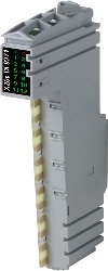
X20cDI9371Description:
- 12 digital inputs
- Sink connection
- 1-wire connections
- Software input filter can be configured for entire module
The module is equipped with 12 inputs for 1-wire connections. The module is designed for sink input wiring.
Accessoires obligatoires
| Automation Studio HW Upgrades | Version (date) | Téléchargement |
|---|---|---|
| V3.0 HW Upgrade (X20cDI9371) | EXE / 838 Ko | |
| V4.0 HW Upgrade (X20cDI9371) | EXE / 1 Mo |
| Documentation | Version (date) | Téléchargement |
|---|---|---|
| Coated modules | PDF / 62 Ko | |
| Data sheet X20(c)DI9371 | PDF / 898 Ko | |
| X20 Package leaflet ATEX/CSA | PDF / 2 Mo | |
| X20 System User´s Manual | PDF / 49 Mo |
| E-CAD (modèles Electro ou EPLAN) | Version (date) | Téléchargement |
|---|---|---|
| X20 EPLAN P8 from V2.4 | EXE / 160 Mo |
| M-CAD (modèles mécaniques) | Version (date) | Téléchargement |
|---|---|---|
| 3D File DXF/STEP X20 Electronic module | ZIP / 10 Ko | |
| 3D File STEP X20 I/O-Slice | ZIP / 872 Ko | |
| Dimensions PDF X20 Electronic module | PDF / 3 Ko |