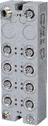
Short description
| I/O module | IO-Link master with 8 IO-Link interfaces |
General information
| B&R ID code | 0x2DB9 |
| Status indicators | IO-Link operating state, bus function, module status |
| Diagnostics | |
| Module run/error | Yes, using LED status indicator and software |
| IO-Link operating state | Yes, using LED status indicator and software |
| C/Q status | Yes, using LED status indicator and software |
| I/Q status | Yes, using LED status indicator and software |
| Connection type | |
| X2X Link | M12, B-coded |
| Inputs | M12, A-coded |
| I/O power supply | M8, 4-pin |
| Cable specification | |
| Cable type | 4-pin sensor cable, unshielded |
| Cable length | Max. 20 m |
| Line capacitance | Max. 3 nF |
| Loop resistance | Max. 6 Ω |
| Power consumption | |
| Internal I/O |
0.8 W via connection C 0.5 W via connection D |
| X2X Link power supply | 0.8 W |
| Additional power dissipation caused by actuators (resistive) [W] | - |
| Certifications | |
| CE | Yes |
| UKCA | Yes |
| CRA (Cyber Resilience Act) | In preparation |
| UL |
cTÜV SÜDus No. U10 041745 0020 Per UL 61010-2-201 |
I/O power supply
| Nominal voltage | 24 VDC |
| Voltage range | 24 VDC ±25% |
| Integrated protective function | Reverse polarity protection |
Sensor/Actuator power supply
| Voltage | I/O power supply minus voltage drop for short-circuit protection |
| Voltage drop for short-circuit protection at 0.5 A | Max. 0.3 V |
| Power consumption | Max. 12 W per IO-Link interface |
| Short-circuit proof | Yes |
| Overload protection | |
| Switch-off delay | Configurable using software |
| Switch-off duration | Configurable using software |
Class B sensor/actuator power supply
IO-Link in master mode
| Transfer rates | |
| COM1 | 4.8 kbaud |
| COM2 | 38.4 kbaud |
| COM3 | 230.4 kbaud |
| Limit values for COM3 | |
| Max. connection capacity | 22 nF (cable + IO-Link device) |
| Max. load | 96 Ω / 250 mA |
| Data format | 1 start bit, 8 data bits, 1 parity bit (even), 1 stop bit |
| Bus level | 24 VDC (active), 0 VDC (resting voltage) |
IO-Link in master mode or in SIO mode "digital output"
| Variant | Bipolar, positive and negative switching |
| Peak short-circuit current | <1.3 A |
| Residual voltage | <0.7 VDC at nominal current 0.25 A |
| Switching voltage | I/O power supply minus voltage drop for short-circuit protection and semiconductor switch |
| Voltage drop on semiconductor switch | Max. 0.5 VDC at 0.25 A |
| Switching delay | |
| 0 → 1 | <10 µs |
| 1 → 0 | <10 µs |
| Overload protection of C/Q output | |
| Overcurrent threshold | Configurable using software |
| Switch-off duration | Configurable using software |
IO-Link in SIO mode "Digital output"
| Nominal voltage | 24 VDC |
| Nominal output current | 0.25 A |
| Total nominal current with actuator power supply | Max. 4 A |
| Output circuit | Sink or source |
| Switching frequency (resistive load) | Max. 500 Hz |
| Output protection | Thermal shutdown in the event of overcurrent or short circuit, integrated protection for switching inductive loads |
IO-Link in SIO mode "digital input"
| Nominal voltage | 24 VDC |
| Input filter | |
| Hardware | 300 ns |
| Input circuit | Sink |
| Input voltage | 24 VDC -15% / +20% |
| Input current at 24 VDC | Typ. 2.4 mA |
| Input resistance | Typ. 10 kΩ |
| Switching threshold | |
| Low | <5 VDC |
| High | >15 VDC |
IO-Link I/Q interface (digital input)
| Nominal voltage | 24 VDC |
| Input voltage | 24 VDC -15% / +20% |
| Input current at 24 VDC | Typ. 3.6 mA |
| Input filter | |
| Hardware | ≤60 µs |
| Software | Default 1 ms, configurable between 0 and 25.5 ms |
| Input circuit | Sink |
| Input resistance | Typ. 6.3 kΩ |
| Switching threshold | |
| Low | <5 VDC |
| High | >15 VDC |
Electrical properties
| Electrical isolation | Bus isolated from IO-Link |
Operating conditions
| Mounting orientation | |
| Any | Yes |
| Installation elevation above sea level | |
| 0 to 2000 m | No limitation |
| >2000 m | Reduction of ambient temperature by 0.5°C per 100 m |
| Degree of protection per EN 60529 | IP67 |
Ambient conditions
| Temperature | |
| Operation | -25 to 60°C |
| Storage | -40 to 85°C |
| Transport | -40 to 85°C |
| Relative humidity | |
| Operation | 5 to 95% |
| Storage | 5 to 95% |
| Transport | 5 to 95% |
Mechanical properties
| Dimensions | |
| Width | 53 mm |
| Height | 155 mm |
| Depth | 42 mm |
| Weight | 450 g |
| Torque for connections | |
| M8 | Max. 0.4 Nm |
| M12 | Max. 0.6 Nm |
Materialenummer:
X67DS838B.L12Beskrivelse:
- 2 IO-Link channels (port class B)
- 6 IO-Link channels (port class A)
- Port class A: Additional digital input per IO-Link connection
- Each IO-Link channel configurable as a digital input or output (SIO mode)
- 24 VDC and GND for sensor/actuator power supply
- Port class B: Additional 24 VDC and GND for sensor/actuator power supply
- NetTime timestamps: IO-Link data
The module is an IO-Link master that allows intelligent sensors and actuators to be connected per the IO-Link standard. The module can operate up to 8 IO-Link devices. All IO-Link channels can also be operated in SIO mode and thus used as digital inputs or outputs. The module is also equipped with 6 additional digital inputs that can be used independently of the configuration of the IO-Link channels. Connectors 7 and 8 are designed as class B IO-Link ports and have an additional galvanically isolated supply voltage.
| Automation Studio HW opgraderinger | Version (dato) | Download |
|---|---|---|
| V4.12 HW Upgrade (X67DS838B.L12) | EXE / 4 MB | |
| V6.0 HW Upgrade (X67DS838B.L12) | EXE / 4 MB |
| Certifikater | Version (dato) | Download |
|---|---|---|
| U10 041745 0020 TÜV SÜD X67 | PDF / 254 KB |
| Dokumentation | Version (dato) | Download |
|---|---|---|
| Data sheet X67DS838B.L12 | PDF / 3 MB | |
| X67 System User´s Manual | PDF / 19 MB |
| E-CAD (Elektro eller EPLAN skabeloner) | Version (dato) | Download |
|---|---|---|
| Makro-/Artikeldaten 4.0.1 (X67DS838B.L12) | EXE / 2 MB |
| M-CAD (Mechan. skabeloner) | Version (dato) | Download |
|---|---|---|
| 3D File DXF/STEP X67 High Density | ZIP / 709 KB |