Short description
| Bus controller | POWERLINK (V1/V2) controlled node |
General information
| B&R ID code | |
| Bus controller | 0x046C |
| Internal I/O module | 0x04A8 |
| Diagnostics | |
| Outputs | Yes, using LED status indicator and software |
| I/O power supply | Yes, using LED status indicator and software |
| Support | |
| Dynamic node allocation (DNA) | Yes |
| Connection type | |
| Fieldbus | M12, D-coded |
| X2X Link | M12, B-coded |
| Inputs/Outputs | 8x M12, A-coded |
| I/O power supply | M8, 4-pin |
| Power consumption | |
| Fieldbus | 2.5 W |
| Internal I/O | 0.6 W |
| X2X Link power supply | 17.25 W at maximum power output for connected I/O modules |
| Certifications | |
| CE | Yes |
| UKCA | Yes |
| CRA (Cyber Resilience Act) | In preparation |
| Inputs/Outputs | 6 digital inputs, 6 digital outputs (not configurable), inputs with additional function, 1 analog channel |
| Insulation voltage between channel and bus | 500 Veff |
| Nominal voltage | 24 VDC |
| Sensor/Actuator power supply | 0.5 A summation current |
| Status indicators | I/O function per channel, supply voltage, bus function |
| Power output | 15 W X2X Link power supply for I/O modules |
Interfaces
I/O power supply
Sensor/Actuator power supply
| Voltage | I/O power supply minus voltage drop for short-circuit protection |
| Voltage drop for short-circuit protection at 0.5 A | Max. 2 VDC |
| Summation current | Max. 0.5 A |
| Short-circuit proof | Yes |
Digital inputs
| Switching threshold | |
| Low | <5 VDC |
| High | >15 VDC |
| Input characteristics per EN 61131-2 | Type 1 |
| Input voltage | 18 to 30 VDC |
| Input current at 24 VDC | Typ. 4 mA |
| Input circuit | Sink |
| Input resistance | Typ. 6 kΩ |
Edge detection / Time measurement
| Counter frequency | |
| Internal | 10 kHz |
| Signal form | Square wave pulse |
| Counter size | 16-bit |
| Pulse length | >200 µs with 200 µs pause between pulses |
| Measurement type | Propagation delay measurement between output and corresponding feedback input |
Analog inputs
Digital outputs
| Switching delay | |
| 0 → 1 | <400 µs |
| 1 → 0 | <400 µs |
| Switching frequency | |
| Resistive load | Max. 100 Hz |
| Inductive load | See section "Switching inductive loads". |
| Variant | Current-sourcing FET |
| Switching voltage | I/O power supply minus residual voltage |
| Nominal output current | 0.5 A |
| Total nominal current | 8 A |
| Output circuit | Source |
| Output protection | Thermal shutdown in the event of overcurrent or short circuit, integrated protection for switching inductive loads, reverse polarity protection of the output power supply |
| Diagnostic status | Output monitoring with 10 ms delay |
| Leakage current when the output is switched off | 5 µA |
| Switching on after overload shutdown | Approx. 10 ms (depends on the module temperature) |
| RDS(on) | 150 mΩ |
| Residual voltage | <0.3 V at 0.5 A nominal current |
| Peak short-circuit current | <12 A |
| Braking voltage when switching off inductive loads | 50 VDC |
Electrical properties
| Electrical isolation |
Bus isolated from POWERLINK and channel Channel not isolated from channel |
Operating conditions
| Mounting orientation | |
| Any | Yes |
| Installation elevation above sea level | |
| 0 to 2000 m | No limitation |
| >2000 m | Reduction of ambient temperature by 0.5°C per 100 m |
| Degree of protection per EN 60529 | IP67 |
Ambient conditions
| Temperature | |
| Operation | -25 to 60°C |
| Derating | - |
| Storage | -40 to 85°C |
| Transport | -40 to 85°C |
Mechanical properties
| Dimensions | |
| Width | 53 mm |
| Height | 155 mm |
| Depth | 42 mm |
| Torque for connections | |
| M8 | Max. 0.4 Nm |
| M12 | Max. 0.6 Nm |
| Weight | 360 g |
物料号:
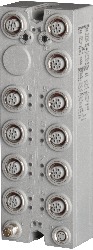
X67BC8513.L12-1描述:
- POWERLINK V1/V2
- Integrated hub for economical wiring
- 12 digital channels, configurable as inputs or outputs
- 1 analog input, 0 to 20 mA, 12-bit
- M8 connection type
- I/O configuration and firmware update via the fieldbus
- Integrated connection to the local expansion via X2X Link for up to 250 additional modules
- Configurable I/O cycle (starting at 200 µs)
The bus controller makes it possible to connect X2X Link I/O nodes to POWERLINK. It is also possible to operate the X2X Link cycle synchronously 1:1 or synchronous to POWERLINK using a prescaler.
Additional X2X Link I/O nodes (X67 modules or other modules based on X2X Link) can be connected using the integrated X2X Link connection. Mechanically, POWERLINK is connected via an IP67-rated standard D-coded M12 Ethernet connector.
POWERLINK is a standard protocol for Fast Ethernet equipped with hard real-time characteristics. The POWERLINK Standardization Group (EPSG) ensures that the standard remains open and is continually developed:: www.ethernet-powerlink.org.
| Automation Studio硬件升级 | 版本(日期) | 下载 |
|---|---|---|
| V4.0 HW Upgrade (X67BC8513.L12-1) | EXE / 2 MB | |
| V6.0 HW Upgrade (X67BC8513.L12-1) | EXE / 2 MB |
| E-CAD(电子或EPLAN模板) | 版本(日期) | 下载 |
|---|---|---|
| Makro-/Artikeldaten 4.0.1 (X67BC8513.L12-1) | EXE / 1 MB |
| 文档 | 版本(日期) | 下载 |
|---|---|---|
| Data sheet X67BC8513.L12-1 | PDF / 6 MB | |
| POWERLINK Bus Controller User's Manual | PDF / 3 MB | |
| X67 System User´s Manual | PDF / 19 MB |
| 证书 | 版本(日期) | 下载 |
|---|---|---|
| EU Declaration ATEX X67 | PDF / 191 KB | |
| EU Declaration PLC X67 | PDF / 674 KB | |
| UK Declaration PLC X67 | PDF / 469 KB |