Short description
| Bus controller | CANopen |
General information
| Inputs/Outputs | 8 digital channels, configurable as inputs or outputs using software, inputs with additional functions |
| Insulation voltage between channel and bus | 500 Veff |
| Nominal voltage | 24 VDC |
| B&R ID code | |
| Bus controller | 0x17D4 |
| Internal I/O module | 0x1311 |
| Sensor/Actuator power supply | 0.5 A summation current |
| Status indicators | I/O function per channel, supply voltage, bus function |
| Diagnostics | |
| Outputs | Yes, using LED status indicator and software |
| I/O power supply | Yes, using LED status indicator and software |
| Connection type | |
| Fieldbus | M12, A-coded |
| X2X Link | M12, B-coded |
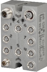
| Inputs/Outputs | 8x M8, 3-pin |
| I/O power supply | M8, 4-pin |
| Power output | 3 W X2X Link power supply for I/O modules |
| Power consumption | |
| Fieldbus | 2.7 W |
| Internal I/O | 2 W |
| X2X Link power supply | 6.6 W at maximum power output for connected I/O modules |
| Certifications | |
| CE | Yes |
| UKCA | Yes |
| ATEX |
Zone 2, II 3G Ex nA IIA T5 Gc IP67, Ta = 0 - Max. 60°C TÜV 05 ATEX 7201X |
| UL |
cULus E115267 Industrial control equipment |
| HazLoc |
cCSAus 244665 Process control equipment for hazardous locations Class I, Division 2, Groups ABCD, T5 |
| KC | Yes |
Interfaces
I/O power supply
Sensor/Actuator power supply
| Voltage | Module power supply minus voltage drop for short-circuit protection |
| Voltage drop for short-circuit protection at 0.5 A | Max. 2 VDC |
| Summation current | Max. 0.5 A |
| Short-circuit proof | Yes |
Digital inputs
| Input voltage | 18 to 30 VDC |
| Input current at 24 VDC | Typ. 4 mA |
| Input circuit | Sink |
| Input filter | |
| Hardware | ≤10 μs (channels 1 to 4) / ≤70 µs (channels 5 to 8) |
| Software | Default 0 ms, configurable between 0 and 25 ms in 0.1 ms intervals |
| Input resistance | Typ. 6 kΩ |
| Additional functions | 50 kHz event counting, gate measurement |
| Switching threshold | |
| Low | <5 VDC |
| High | >15 VDC |
Event counters
| Quantity | 2 |
| Signal form | Square wave pulse |
| Evaluation | Each negative edge, cyclic counter |
| Input frequency | Max. 50 kHz |
| Counter 1 | Input 1 |
| Counter 2 | Input 3 |
| Counter frequency | Max. 50 kHz |
| Counter size | 16-bit |
Gate time measurement
| Quantity | 1 |
| Signal form | Square wave pulse |
| Evaluation | Positive edge - Negative edge |
| Counter frequency | |
| Internal | 48 MHz, 3 MHz, 187.5 kHz |
| Counter size | 16-bit |
| Length of pause between pulses | ≥100 µs |
| Pulse length | ≥20 µs |
| Supported inputs | Input 2 or input 4 |
Digital outputs
| Variant | Current-sourcing FET |
| Switching voltage | Module power supply minus residual voltage |
| Nominal output current | 0.5 A |
| Total nominal current | 4 A |
| Output circuit | Source |
| Output protection | Thermal shutdown in the event of overcurrent or short circuit, integrated protection for switching inductive loads, reverse polarity protection of the output power supply |
| Diagnostic status | Output monitoring with 10 ms delay |
| Leakage current when the output is switched off | 5 µA |
| Switching on after overload shutdown | Approx. 10 ms (depends on the module temperature) |
| Residual voltage | <0.3 V at 0.5 A nominal current |
| Peak short-circuit current | <12 A |
| Switching delay | |
| 0 → 1 | <400 µs |
| 1 → 0 | <400 µs |
| Switching frequency | |
| Resistive load | Max. 100 Hz |
| Inductive load | See section "Switching inductive loads". |
| Braking voltage when switching off inductive loads | 50 VDC |
Electrical properties
| Electrical isolation |
Channel isolated from CANopen and bus CANopen not isolated from bus and channel not isolated from channel
|
Operating conditions
| Mounting orientation | |
| Any | Yes |
| Installation elevation above sea level | |
| 0 to 2000 m | No limitation |
| >2000 m | Reduction of ambient temperature by 0.5°C per 100 m |
| Degree of protection per EN 60529 | IP67 |
Ambient conditions
| Temperature | |
| Operation | 0 to 60°C |
| Derating | - |
| Storage | -25 to 85°C |
| Transport | -25 to 85°C |
Mechanical properties
| Dimensions | |
| Width | 53 mm |
| Height | 85 mm |
| Depth | 42 mm |
| Weight | 200 g |
| Torque for connections | |
| M8 | Max. 0.4 Nm |
| M12 | Max. 0.6 Nm |
Número do material:
X67BC4321Descrição:
- Fieldbus: CANopen
- 8 digital channels, can be configured as input or output
- Simple I/O configuration via the fieldbus
- Integrated connection to the local expansions via X2X Link for 39 additional modules
- Configurable I/O cycle (0.4 to 1.3 ms)
CAN (Controller Area Network) has become considerably widespread in automation technology. CAN topology is based on a line structure and uses twisted pair wires for data transfer. CANopen is a higher-layer protocol based on CAN. This standardized protocol offers highly flexible configuration possibilities.
This bus controller makes it possible to connect X2X Link I/O nodes to CANopen. The bus controller has automatic transfer rate detection and AutoMapping of the I/O modules connected with X2X Link. All CANopen operating modes such as synchronous, event and polling modes are supported together with PDO linking, life/node guarding, emergency objects and much more.
Note: | Only the default function model is supported (see respective module description) by the bus controller for multi-function modules. |
| Arquivo com descritivo do equipamento de campo | Version (Data) | Download |
|---|---|---|
| X67BC4321 EDS Package | ZIP / 108 KB |
| Certificados | Version (Data) | Download |
|---|---|---|
| 2226379 CSA Certificate of Compliance X20 X67 | PDF / 385 KB | |
| E115267 UL CoC X67 | PDF / 345 KB | |
| TÜV 05 ATEX 7201 X | PDF / 5 MB | |
| X20, X67 KC certificates | PDF / 6 MB |
| Documentação | Version (Data) | Download |
|---|---|---|
| Datasheet X67BC4321 | PDF / 1 MB |
| E-CAD (Modelos Electro ou EPLAN) | Version (Data) | Download |
|---|---|---|
| X67 EPLAN P8 from V2.4 | EXE / 105 MB |
| M-CAD (Mechan. Modelos) | Version (Data) | Download |
|---|---|---|
| 3D File DXF/STEP X67 | ZIP / 1 MB |