Short description
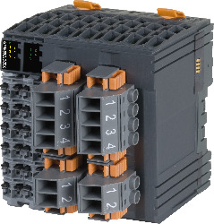
| I/O module | X20 energy measurement and synchronization module |
General information
Digital outputs
| Switching delay | |
| 0 → 1 | <300 μs |
| 1 → 0 | <300 μs |
| Switching frequency | |
| Resistive load | Max. 100 Hz |
| Quantity | 5 |
| Variant | Current-sourcing FET |
| Nominal voltage | 24 VDC |
| Switching voltage | 24 VDC -15% / +20% |
| Nominal output current | 0.1 A |
| Total nominal current | 0.5 A |
| Connection type | 1-wire connections |
| Output circuit | Source |
| Output protection | Thermal shutdown in the event of overcurrent or short circuit |
| Diagnostic status | Output monitoring with 10 ms delay |
| Leakage current when the output is switched off | 5 μA |
| Residual voltage | <0.3 V at 0.1 A nominal current |
| Peak short-circuit current | <2 A |
| Switch-on in the event of overload shutdown or short-circuit shutdown | Approx. 10 ms, depends on the module temperature |
| Insulation voltage between channel and bus | 500 Veff |
Relay outputs
Analog input voltage
Analog input current
Electrical properties
| Electrical isolation |
Bus isolated from I/O power supply and digital inputs and outputs Digital inputs and outputs isolated from each other |
Operating conditions
| Mounting orientation | |
| Horizontal | Yes |
| Vertical | Yes |
| Installation elevation above sea level | |
| 0 to 2000 m | No limitation |
| >2000 m | Reduction of ambient temperature by 0.5°C per 100 m |
| Degree of protection per EN 60529 | IP20 |
Ambient conditions
| Temperature | |
| Operation | |
| Horizontal mounting orientation | -25 to 60°C |
| Vertical mounting orientation | -25 to 50°C |
| Derating | See section "Derating". |
| Storage | -40 to 85°C |
| Transport | -40 to 85°C |
| Relative humidity | |
| Operation | 5 to 95%, non-condensing |
| Storage | 5 to 95%, non-condensing |
| Transport | 5 to 95%, non-condensing |
Mechanical properties
| Note |
Order 2x terminal block X20TB12 separately. Order 2x screw clamp terminal block TB3102 and 2x screw clamp terminal block TB3104 separately. |
| Pitch | 87.5+0.2 mm |
Materiaalnummer:
X20CM0985-02Omschrijving:
- Energy measurement for 120 to 480 VAC
- Simultaneous measurement of 2 AC power systems plus 2 additional voltages
- For multifunction measurement tasks
- Intelligent power system synchronization unit
- Current values of generator voltage and current
- Monitor functions per current power system guidelines
Vereiste toebehoren
Terminal blocks
| 0TB3102-7011 | X20 digital and analog mixed module, multi-measurement transducer / synchronization module, 5 digital outputs, 24 VDC, 0.5 A, source, 1 relay, 1 A, 8 analog inputs, ±480 V / 120 V, 16-bit converter resolution, 3 analog inputs, 5 A / 1 A AC, 16-bit converter resolution, additional software functionalities, adapted to VDE guidelines (2018), order terminal blocks 0TB3102-7011, 0TB3104-7011, 0TB3102-7012, 0TB3104-7012 and 2x X20TB12 separately! |
| 0TB3102-7012 | X20 digital and analog mixed module, multi-measurement transducer / synchronization module, 5 digital outputs, 24 VDC, 0.5 A, source, 1 relay, 1 A, 8 analog inputs, ±480 V / 120 V, 16-bit converter resolution, 3 analog inputs, 5 A / 1 A AC, 16-bit converter resolution, additional software functionalities, adapted to VDE guidelines (2018), order terminal blocks 0TB3102-7011, 0TB3104-7011, 0TB3102-7012, 0TB3104-7012 and 2x X20TB12 separately! |
| 0TB3104-7011 | X20 digital and analog mixed module, multi-measurement transducer / synchronization module, 5 digital outputs, 24 VDC, 0.5 A, source, 1 relay, 1 A, 8 analog inputs, ±480 V / 120 V, 16-bit converter resolution, 3 analog inputs, 5 A / 1 A AC, 16-bit converter resolution, additional software functionalities, adapted to VDE guidelines (2018), order terminal blocks 0TB3102-7011, 0TB3104-7011, 0TB3102-7012, 0TB3104-7012 and 2x X20TB12 separately! |
| 0TB3104-7012 | X20 digital and analog mixed module, multi-measurement transducer / synchronization module, 5 digital outputs, 24 VDC, 0.5 A, source, 1 relay, 1 A, 8 analog inputs, ±480 V / 120 V, 16-bit converter resolution, 3 analog inputs, 5 A / 1 A AC, 16-bit converter resolution, additional software functionalities, adapted to VDE guidelines (2018), order terminal blocks 0TB3102-7011, 0TB3104-7011, 0TB3102-7012, 0TB3104-7012 and 2x X20TB12 separately! |
| X20TB12 | X20 digital and analog mixed module, multi-measurement transducer / synchronization module, 5 digital outputs, 24 VDC, 0.5 A, source, 1 relay, 1 A, 8 analog inputs, ±480 V / 120 V, 16-bit converter resolution, 3 analog inputs, 5 A / 1 A AC, 16-bit converter resolution, additional software functionalities, adapted to VDE guidelines (2018), order terminal blocks 0TB3102-7011, 0TB3104-7011, 0TB3102-7012, 0TB3104-7012 and 2x X20TB12 separately! |
| Automation Studio HW Upgrades | Versie (Datum) | Download |
|---|---|---|
| V4.2 HW Upgrade (X20CM0985-02) | EXE / 4 MB | |
| V6.0 HW Upgrade (X20CM0985-02) | EXE / 4 MB |
| Documentatie | Versie (Datum) | Download |
|---|---|---|
| Data sheet X20CM0985-02 | PDF / 3 MB | |
| X20 System User´s Manual | PDF / 49 MB |
| E-CAD (Electro of EPLAN Templates) | Versie (Datum) | Download |
|---|---|---|
| X20 EPLAN P8 from V2.4 | EXE / 160 MB |
| M-CAD (Mechan. Templates) | Versie (Datum) | Download |
|---|---|---|
| 3D data DXF / STEP X20CM0985 | ZIP / 1 MB |