Short description
| Interfaces | 1x Ethernet, 1x USB, 3x CAN bus, 1x POWERLINK |
| System module | Controller |
General information
Input power supply
Controller
Interfaces
Multi-function inputs
| Multifunction digital inputs (MF-DI) | |
| Quantity | 4 |
| Functions |
Sink/Source circuit - Configurable per channel, configurable software input filter, counter function up to 50 kHz counter frequency (AB, ABR, DF, edge counter), edge detection with timestamp (for period duration, gate measurement, differential time measurement) |
| Multifunction analog inputs (MF-AI) | |
| Quantity | 8 |
| Functions |
Sink/Source circuit - Configurable per channel, configurable software input filter, fixed or ratiometrically configurable switching threshold, open-circuit and short-circuit detection. Configurable software input filter, open-circuit and short-circuit detection. Measurement range 0 to 10 V / 0 to 32 V / 0 to 20 mA / 4 to 20 mA / 1 to 50 kΩ / temperature inputs (Pt1000 characteristic curve), configurable analog filter, configurable ramp limit, configurable threshold values, integrated input protection |
Multi-function outputs
| Multifunction digital outputs (MF-DO) | |
| Quantity | 4 |
| Functions |
4 A nominal current, source circuit, integrated output protection per channel, configurable overload monitoring per channel, central cutoff via relay, parallel connection, current measurement, error state with configurable error filter. Sink/Source circuit configurable per channel, configurable software input filter |
| Multifunction PWM outputs (MF-PWM) | |
| Quantity |
PWM 4 A: 6 PWM 6 A: 2 |
| Functions |
4 A nominal current (PWM 4 A), 6 A nominal current (PWM 6 A), sink/source circuit, integrated output protection per channel, configurable overload monitoring per channel, central cutoff via relay, parallel connection, current measurement, error state with configurable error filter. 4 A nominal current (PWM 4 A), 6 A nominal current (PWM 6 A), PWM frequency 15 Hz to 4 kHz, sink/source circuit, integrated output protection per channel, configurable overload monitoring per channel, central cutoff via relay, parallel connection, current measurement (asynchronous or synchronous to PWM period), configurable load current distribution of PWM outputs, dither. 4 A nominal current (PWM 4 A), 6 A nominal current (PWM 6 A), PWM frequency 15 Hz to 8 kHz (at load), integrated output protection per channel, configurable overload monitoring per channel, central cutoff via relay, parallel connection, current measurement (asynchronous or synchronous to PWM period), configurable load current distribution of PWM outputs, dither. Sink/Source circuit configurable per channel, configurable software input filter |
Digital inputs
Analog inputs
Sensor power supply
Digital outputs
PWM output
Electrical properties
Operating conditions
Ambient conditions
| Temperature | |
| Operation | |
| Horizontal mounting orientation | -40 to 85°C housing surface |
| Vertical mounting orientation | -40 to 85°C housing surface |
| Derating | See section "Derating". |
| Storage | -40 to 85°C |
| Transport | -40 to 85°C |
| Relative humidity | |
| Operation | 5 to 100%, condensing |
| Storage | 5 to 95%, non-condensing |
| Transport | 5 to 95%, non-condensing |
Brief overview
| Content of delivery | 2x protective covers for unused female M12 connectors |
Número de material:
X90CP174.24-00Descripción:
- Agricultural and forestry machines
- Construction equipment
- Municipal utility vehicles
- Stationary outdoor applications
- Powerful ARM CPU with 650 MHz
- Multifunction I/O channels
- Ethernet, POWERLINK, 3x CAN bus, USB
- Modular expansion
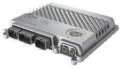
The heart of the X90 mobile system is a controller with a powerful ARM processor and up to 24 multifunction I/O channels. Basic features include interfaces for CAN, USB, Ethernet and the real-time POWERLINK bus system.
The extremely robust die-cast aluminum housing provides space for up to 4 additional expansion boards. These make it possible to add I/O channels or interfaces as well as specific functions such as condition monitoring.
Accesorios opcionales
Analog inputs
| X90AISG0.02-00 | X90 mobile option board, strain gauge module for 2 DMS full-bridge strain gauges, 24-bit converter resolution, 5 kHz input filter |
Analog outputs
| X90AO410.08-00 | X90 mobile option board AO, 8 analog outputs, 12-bit, optional 0 to 10 V / 0 to 20 mA, optional DI, 9 to 32 VDC, sink/source, configuration using software |
| X90AO410.04-00 | X90 mobile option board AO, 4 analog outputs, 12-bit, optional 0 to 10 V / 0 to 20 mA, optional DI, 9 to 32 VDC, sink/source, configuration using software |
BreakOut Box
| X90AC-BB.17-00 | X90 breakout box for X90CP17x development and tests |
CMC connector
| X90TB100.03-00 | X90 CMC connector set for X90CP17x, with connector contacts and dummy plugs |
Communication modules
| X90IF7L0.05-00 | X90 mobile IF option board, 3x CAN, 2x LIN (master), configuration using software |
| X90IF730.04-00 | X90 mobile IF option board, 3x CAN, 1x RS485, configuration using software |
| X90IF720.04-00 | X90 mobile IF option board, 3x CAN, 1x RS232 configuration using software |
| X90DSI00.04-00 | X90 IO-Link option board, digital signal module, 4x IO-Link master, 4 digital channels configurable as inputs or outputs, 3-wire connections |
Condition Monitoring
| X90CM480.04-00 | X90 mobile condition monitoring, option board for vibration measurement and vibration analysis of condition monitoring tasks, 4 IEPE analog inputs |
Digital inputs
| X90DI110.10-00 | X90 mobile option board DI, 10 digital inputs, 9 to 32 VDC, optional sink/source, optional counter input 50 kHz or AB encoder, configuration using software |
Digital outputs
| X90RO440.05-00 | X90 mobile option board relay, 5 relays, normally open contact, for external actuator power supply, 9 to 32 VDC / 2 A |
| X90PO210.08-00 | X90 mobile option board PWM, 8x PWM outputs, 9 to 32 VDC, max. 4 A, with current measurement (12-bit), 15 Hz to 1 kHz, optional DI, 9 to 32 VDC, sink/source, configuration using software |
Motor modules
| X90SM546.02-01 | X90 stepper motor module, with current reduction function, module power supply 15 to 32 VDC, 2 motor connections,4 A continuous current, 8 A peak current, NetTime function |
Safe digital outputs
| X90RO440.04-S1 | X90 mobile option board with safe relay outputs, 4 relays, normally open contacts, for external actuator power supply, 9 to 32 VDC / 2 and 4 A |
Temperature measurement
| X90AT910.08-00 | X90 mobile option board AT, 8 resistance measurement inputs, Pt1000, optional DI, 9 to 32 VDC, sink/source, optional AI, 0 to 10 V / 0 to 32 V, 0 to 20 mA, optional PWM output, 9 to 32 VDC, 10 mA, 1 kHz, configuration using software |
| X90AT910.04-00 | X90 mobile option board AT, 4 resistance measurement inputs, Pt1000, optional DI, 9 to 32 VDC, sink/source, optional AI, 0 to 10 V / 0 to 32 V, 0 to 20 mA, optional PWM output, 9 to 32 VDC, 10 mA, 1 kHz, configuration using software |
Wire harness
| X90CA100.02-00 | X90 wiring harness starter set for X90CP17x, 2 m, for CMC header |
| Actualizaciones de hardware de Automation Studio | Versión (fecha) | Descargar |
|---|---|---|
| V4.12 HW Upgrade (X90CP174.24-00) | EXE / 6 MB | |
| V4.3 HW Upgrade (X90CP174.24-00) | EXE / 4 MB | |
| V4.7 HW Upgrade (X90CP174.24-00) | EXE / 6 MB | |
| V4.9 HW Upgrade (X90CP174.24-00) | EXE / 6 MB | |
| V6.0 HW Upgrade (X90CP174.24-00) | EXE / 6 MB |
| Documentación | Versión (fecha) | Descargar |
|---|---|---|
| Datasheet X90CP174.xx-00 | PDF / 11 MB | |
| Open Source Licenses X90CPxxxx | ZIP / 1 MB | |
| X90 mobile System User´s Manual | PDF / 27 MB | |
| X90 pin allocation CMC connector | ZIP / 3 MB |
| E-CAD (plantillas Electro o EPLAN) | Versión (fecha) | Descargar |
|---|---|---|
| X90 EPLAN P8 from V2.4 | EXE / 69 MB |
| M-CAD (plantillas mecánicas) | Versión (fecha) | Descargar |
|---|---|---|
| 3D File STEP, DXF X90CP174.xx-00 | ZIP / 12 MB |