Short description
| Interfaces | 1x Ethernet/POWERLINK (switchable), 1x POWERLINK, 3x CAN bus, 1x LIN bus, 1x RS232, 1x USB |
| System module | Controller |
General information
Input power supply
Controller
Interfaces
Multi-function inputs
| Multifunction digital inputs MF-DI (std) | |
| Quantity | 2 |
| Function |
Digital input Sink/Source circuit - Configurable per channel, configurable software input filter |
| Multifunction digital inputs MF-DI (CI) | |
| Quantity | 8 |
| Function |
Digital input Sink/Source circuit - Configurable per channel, configurable software input filter, counter function up to 50 kHz counter frequency (max. 4x AB, max. 2x ABR, max. 2x DF, max. 8x edge counter), edge detection with timestamp (for period duration, gate time measurement, differential time measurement) |
| Multifunction analog inputs MF-AI (std) | |
| Quantity | 4 |
| Function |
Digital input Sink/Source circuit - Configurable per channel, configurable software input filter, fixed or ratiometrically configurable switching threshold. Analog input Measurement range 0 to 10 V / 0 to 32 V / 0/4 to 20 mA, configurable analog filter, configurable ramp limit, configurable threshold values, integrated input protection |
| Multifunction analog inputs MF-AI (AT) | |
| Quantity | 8 |
| Function |
Digital input (without diagnostics) Sink/Source circuit - Configurable per channel, configurable software input filter, fixed or ratiometrically configurable switching threshold. Digital input (with diagnostics) Configurable software input filter, open-circuit and short-circuit detection. Analog input Measurement range 0 to 10 V / 0 to 32 V / 0/4 to 20 mA / 0 to 4000 Ω / temperature inputs (Pt1000 characteristic curve), configurable analog filter, configurable ramp limit, configurable threshold values, integrated input protection |
| Multifunction analog inputs MF-AI (PVG) | |
| Quantity | 8 |
| Function |
Digital input (without diagnostics) Sink/Source circuit - Configurable per channel, configurable software input filter, fixed or ratiometrically configurable switching threshold. Digital input (with diagnostics) Configurable software input filter, open-circuit and short-circuit detection. Analog input Measurement range 0 to 10 V / 0 to 32 V / 0/4 to 20 mA / 0 to 4000 Ω / temperature inputs (Pt1000 characteristic curve), configurable analog filter, configurable ramp limit, configurable threshold values, integrated input protection Ratiometric analog output (smoothed PWM signal) Short-circuit current 5.5 mA max. at 24 V, PWM frequency 25 kHz PVG Short-circuit current 5.5 mA max. at 24 V, PVG frequency 25 kHz. |
Multi-function outputs
| Multifunction digital outputs (MF-DO) | |
| Quantity | 8 |
| Functions |
4 A nominal current, source circuit, integrated output protection per channel, configurable overload monitoring per channel, central cutoff via relay, parallel connection, current measurement, error state with configurable error filter. Sink/Source circuit configurable per channel, configurable software input filter |
| Multifunction PWM outputs MF-PWM (std) | |
| Quantity | 16 |
| Function |
Digital output 4 A nominal current, source circuit, integrated output protection per channel, configurable overload monitoring per channel, central cutoff via relay,parallel connection, current measurement, error state with configurable error filter. PWM output 4 A nominal current, PWM frequency 15 Hz to 1 kHz, source circuit, integrated output protection per channel, configurable overload monitoring per channel, central cutoff via relay, parallel connection, current measurement, configurable switching edge shift to avoid load peaks, dither. Digital input Sink/Source circuit configurable per channel, configurable software input filter |
| Multifunction PWM outputs MF-PWM (bridge) | |
| Quantity | 6 |
| Function |
Digital output 6 A nominal current, push-pull circuit, integrated output protection per channel, configurable overload monitoring per channel, central cutoff via relay,parallel connection, current measurement, error state with configurable error filter. PWM output 6 A nominal current, PWM frequency 15 Hz to 4 kHz, 8 kHz in full-bridge mode, push-pull circuit, integrated output protection per channel, configurable overload monitoring per channel, central cutoff via relay, parallel connection, current measurement, configurable load current distribution of the PWM outputs, dither. Digital input Sink/Source circuit configurable per channel, configurable software input filter |
Digital inputs
Analog inputs
Digital outputs
PWM output
Status outputs
| Quantity | 1 |
| Variant | Connection A2 - Source |
| RDS(on) | 1.4 Ω |
| Max. continuous current | 20 mA |
Electrical properties
| Summation current | |
| Complete system | Max. 30 A |
| Inrush current | Typ. 500 A for <300 µs |
| Electrical isolation | Ethernet (IF2) and POWERLINK (IF3) isolated from each other and from other interfaces |
Operating conditions
Ambient conditions
| Temperature | |
| Operation | |
| Horizontal mounting orientation | -40 to 85°C housing surface |
| Vertical mounting orientation | -40 to 85°C housing surface |
| Derating | See section "Derating". |
| Storage | -40 to 85°C |
| Transport | -40 to 85°C |
| Relative humidity | |
| Operation | 5 to 100%, condensing |
| Storage | 5 to 95%, non-condensing |
| Transport | 5 to 95%, non-condensing |
Mechanical properties
| Dimensions | |
| Width | 225 mm |
| Length | 219.5 mm |
| Height | 43.5 mm |
| Weight | Max. 1740 g |
Brief overview
| Content of delivery | 2x protective covers for unused female M12 connectors |
Material number:
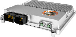
X90CP154.60-00Description:
X90 mobile controller, ARM Cortex A9-650, 256 MB DDR3 RAM, 32 kB FRAM, 4 GB flash memory, 1 POWERLINK to M12, 1 Ethernet 10/100BASE-T to M12, 3 CAN on CMC header, 1 LIN on CMC header, 1 RS232 on CMC header, 60 multifunction I/O, 1 sensor power supply, die-cast aluminum housing, service access window, LED status indicators
Optional Accessories
BreakOut Box
| X90AC-BB.15-00 | X90 breakout box for X90CP15x development and tests |
CMC connector
| X90TB150.02-00 | X90 CMC connector set for X90CP15x, with connector contacts and dummy plugs |
Wire harness
| X90CA150.02-00 | X90 wiring harness starter set for X90CP15x, 2 m, for CMC header |
| Automation Studio HW Upgrades | Version (Date) | Download |
|---|---|---|
| V4.12 HW Upgrade (X90CP154.60-00) | EXE / 5 MB | |
| V6.3 HW Upgrade (X90CP154.60-00) | EXE / 5 MB |
| E-CAD (Electro or EPLAN Templates) | Version (Date) | Download |
|---|---|---|
| X90 EPLAN P8 from V2.4 | EXE / 69 MB |
| M-CAD (Mechan. Templates) | Version (Date) | Download |
|---|---|---|
| 3D File STEP X90CP15x.xx-xx | ZIP / 2 MB |
| Technology Libraries | Version (Date) | Download |
|---|---|---|
| V4.12 CP Upgrade (CpLin) | EXE / 5 MB | |
| V4.12 Library Upgrade (CpLin) | EXE / 3 MB | |
| V6.0 CP Upgrade (CpIsobus) | EXE / 5 MB | |
| V6.0 CP Upgrade (CpLin) | EXE / 5 MB | |
| V6.0 Library Upgrade (CpLin) | EXE / 3 MB |