The market for electric motors is booming, and the ongoing e-mobility trend is not the only reason – demand in industrial applications is also growing steadily. When developing a semi-automated production line for electric motors, risomat found that the complexity of its safety logic was hampering productivity. The solution: visualizing system states using the software modeling language UML (Unified Modeling Language).
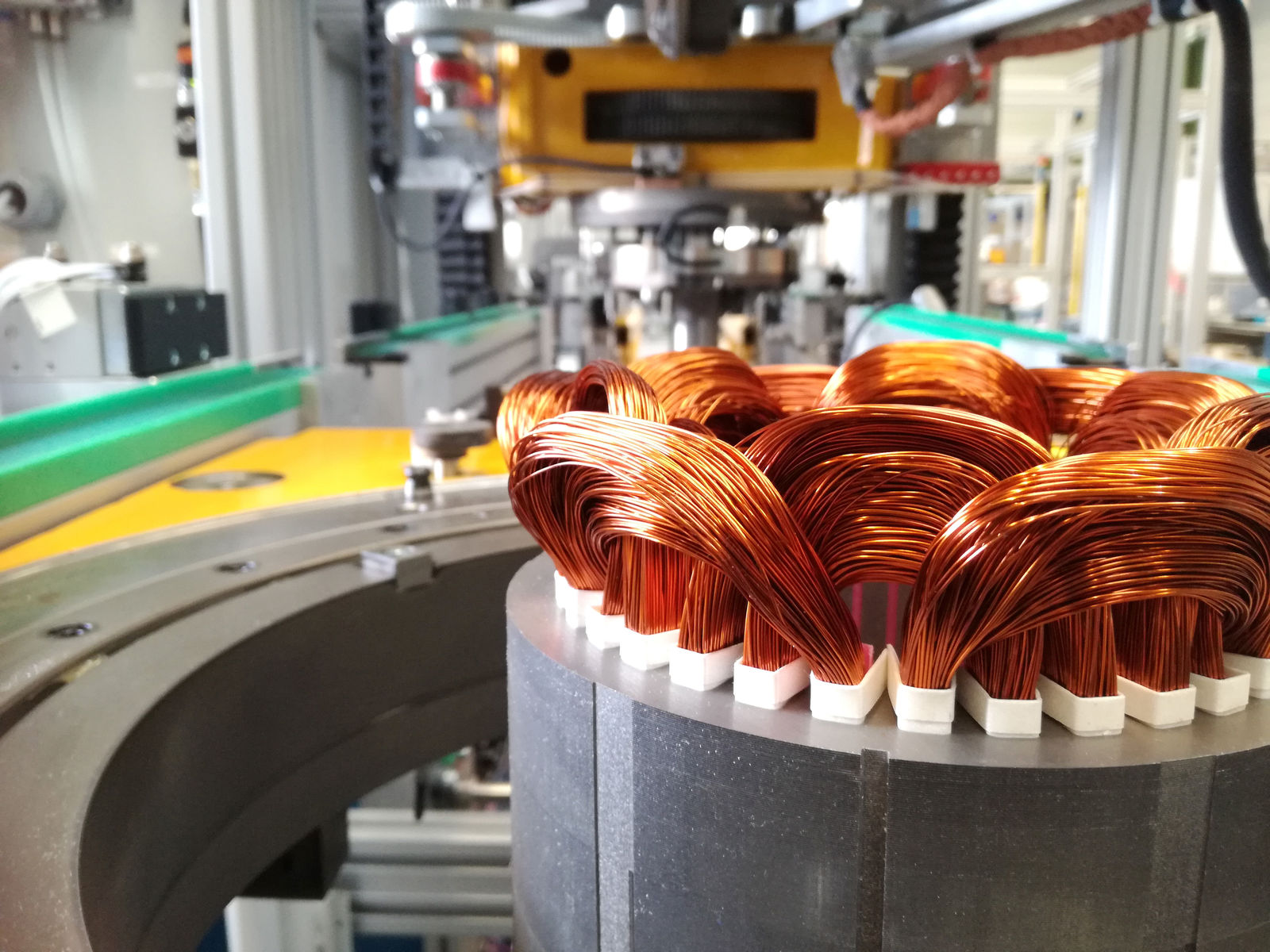
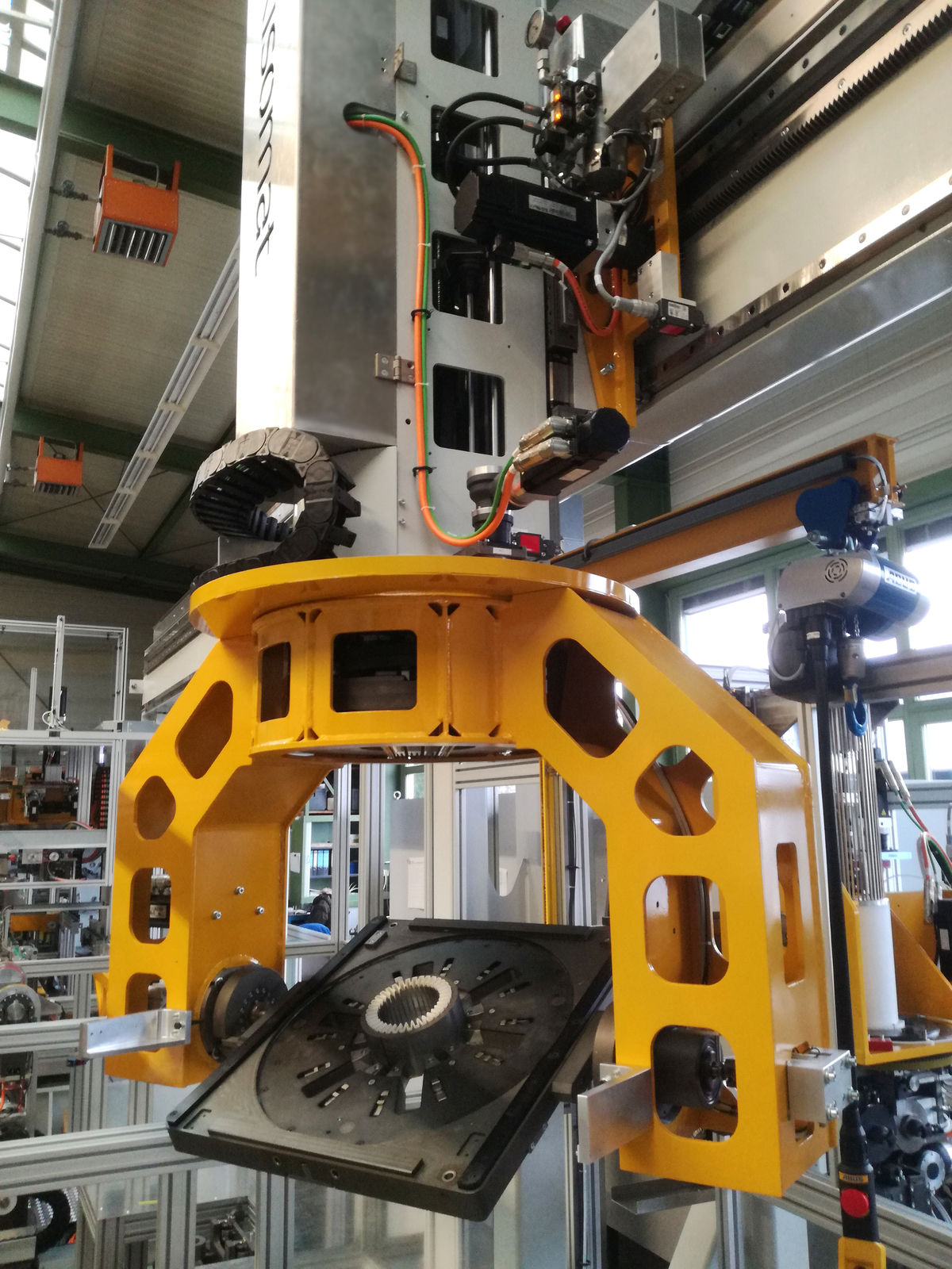
"Our new concept for manufacturing electric motor stators is based on a patented gantry crane that provides functions required at various workstations – such as turning, slewing, clamping and positioning. Equipped with its own tools as well, it also performs processing tasks. "This simplifies the design of the workstations and makes the whole line much more flexible," says risomat's managing director, Hubert Halder, describing a key feature of the new production line. Based in Baienfurt, Germany, his company builds specialty machines for the manufacture of electric motors, generators, pumps, automotive components and linear motors, and is one of Europe's technology leaders in this special field. The line with a gantry crane is designed to produce stators of varying diameters and lengths flexibly and efficiently in small quantities.
The use of a gantry crane brought risomat numerous advantages in terms of design and functionality. To fully utilize the system's potential, however, they needed an intelligent safety solution. "These lines are designed so that processing modules not currently being served by the gantry crane can be used as manual workstations," explains Halder. "This requires dividing the line into safety zones and taking the position of the gantry crane into account so that an emergency stop in one zone doesn't bring the entire machine to a standstill. For our customers, this is of course not a workable solution." Since risomat has been using automation solutions from B&R for many years, it was clear from the start of the project that the controls for the new line would come from B&R. risomat engaged a B&R Qualified Partner to implement the entire solution for machine and safety control. The choice fell on Pantec Automation, a system manufacturer for control solutions in machine and plant construction based in Liechtenstein.
Safety challenges
"The dynamic safety zones weren't the only challenge we faced," recalls Halder. "For technical reasons, we needed to equip both the gantry crane and the processing modules with autonomous PLCs and safety controllers. This meant setting up a higher level of safety communication.
Integrated safety technology from B&R
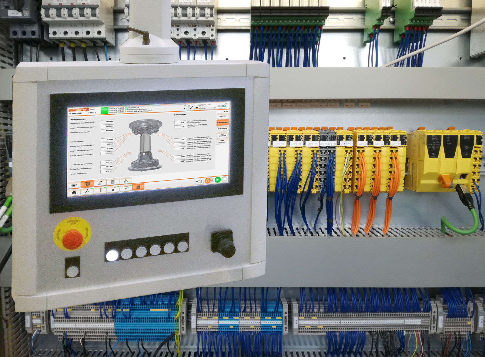
For Pantec project manager Florian Hartmann, however, the question of safety communication had a pragmatic answer. "B&R offers a complete range of control and safety technology that is perfectly suited to creating modular systems," says Hartmann. "Even with a hierarchical structure, there are never any conflicts between systems, and all the components can be programmed with B&R's Automation Studio software." The safety controller is comprised of an X20SL8100 SafeLOGIC together with IP20 and IP67 safety modules.
The solution satisfies PL e or SIL 3. Two safe axes are also used in the gantry crane, because the vertical and horizontal position of the crane has safety implications for processing at the individual stations. Other safety equipment includes light curtains, 2D laser scanners and pressure-sensitive safety mats.
The challenge of dynamic safety zones
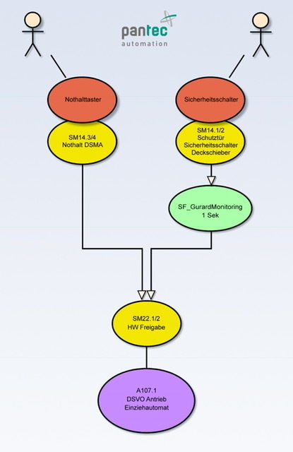
Hartmann and his team soon realized that a classic text-based description of the safety logic was not sufficient to describe the system states completely and transparently. The path to a solution was paved by the idea to derive and describe the safety states using UML, which Pantec's software developers regularly use for things like dynamic state descriptions. Based on the UML approach, a three-stage safety process was developed that describes the path from the approved safety concept to the tested safety controller. This process makes it possible to develop and document a safety application in a transparent way. As a result, the functionality of the safety controller can be tested and documented seamlessly during the acceptance process.
The three-stage UML safety process in detail
In the first stage of the process, the safety components incorporated in the electrical plan are represented in UML as use cases. Then the safety logic is developed. In doing so, the developers define which use case leads to which safety status. This step requires close cooperation between software developers, safety officers and designers. One priority here is to define the safety status in such a way that local emergency stop functions don't affect overall machine operation any more than necessary.
In the second stage of the UML safety process, the modeled safety application is coded and the acceptance test is derived directly from the use cases. In addition to the logic, acceptance testing also covers all the safety hardware and its wiring.
In the third stage, acceptance testing is carried out and the safety system is then approved by the safety officer. Halder finds the model impressive from several perspectives: "On the one hand, the UML safety process allows me to offer my customers higher machine availability."
New B&R innovations for risomat
In addition to safety controller modeling with UML, Pantec Automation took further innovative steps for risomat during the development of the stator production line. One significant step was the development of a completely modular software framework. The ability to automatically generate B&R control code significantly reduced the time and effort required to develop the software for the machine. This was also their first project using B&R's mapp components.
Overall system performance was increased by switching to a B&R Automation PC 2100 controller.
The HMI got an upgrade as well, now using a 15.4" panel with B&R's SDL3 connection technology. In addition, the existing operating concept was subjected to usability analysis and optimized. The results were incorporated into a style guide for future risomat operator panels.
Advantages of UML (Unified Modeling Language) at a glance
- Highlights
- Conceptual design phase: The UML model greatly simplifies communication between software engineers and mechanical engineers. It provides a clear overview and facilitates additions and changes.
- Acceptance phase: The UML visualization makes it easy to plan comprehensive test cases. Acceptance testing is documented seamlessly and transparently. The well structured process shortens the time required for testing.
- Operational phase: The simple visualization in UML provides both operator and service technician a quick overview of how the programmable logic controller works and what functions are available.
 | Hubert Halder Managing Director, risomat GmbH "The UML safety process allows me to offer my customers higher machine availability and gives me excellent transparency with regard to the safety controller." |
 | Florian Hartmann Project Manager, Pantec Engineering AG "The perfectly orchestrated B&R portfolio lets you weave modular safety technology seamlessly into the control system. |