Short description
| I/O module | 6 relays with 1 normally open contact each, 230 VAC / 2 A (6 A), 24 VDC / 6 A |
General information
Safety characteristics
| Note | See section "Safety characteristics". |
I/O power supply
| Nominal voltage | 24 VDC |
| Voltage range | 24 VDC -15% / +20% |
| Integrated protective function | Reverse polarity protection |
Relay outputs
| Quantity | 6 |
| Variant | Relay / Normally open contact, internal high-side and low-side control |
| Nominal output current | 5 mA to 6 A (hardware revision <B5: 2 A) |
| Diagnostic status | Contact position determined by positively driven contacts |
| Max. switching frequency | See section "Inrush current behavior for output channels". |
| Switching delay | |
| 0 → 1 | <50 ms |
| 1 → 0 |
<50 ms Hardware upgrade 2.2.0.0 or later: <20 ms |
| Insulation voltage between channel and bus | Safe disconnection of 300 VAC per EN 50178 |
| Insulation voltage between channel and channel | Tested at 1350 VAC |
| Contact resistance (without terminal block) | 20 mΩ |
| Contact service life | See "Contact service life". |
| Short-circuit/Overload protection | External 6 A gL/gG fuse (melting fuse), LS automat C characteristic 1.6 A |
| Switching voltage range | 5 to 24 VDC, 5 to 230 VAC |
| Coil voltage | 24 VDC -15% / +20% |
| Short-circuit proof | Yes, 1000 A (with specified short-circuit/overload protection) |
| Max. inrush current | AC: 50 A for 100 ms, DC: 10 A for 200 ms |
| Overvoltage category per EN 60664-1 | II |
| Max. switching capacity | |
| UL 508 | B300 / R300 |
Operating conditions
| Mounting orientation | |
| Horizontal | Yes |
| Vertical | Yes |
| Installation elevation above sea level | 0 to 2000 m, no limitation |
| Degree of protection per EN 60529 | IP20 |
Ambient conditions
| Temperature | |
| Operation | |
| Horizontal mounting orientation | 0 to 60°C |
| Vertical mounting orientation | 0 to 50°C |
| Derating | See section "Derating". |
| Storage | -40 to 85°C |
| Transport | -40 to 85°C |
| Relative humidity | |
| Operation | 5 to 95%, non-condensing |
| Storage | 5 to 95%, non-condensing |
| Transport | 5 to 95%, non-condensing |
Mechanical properties
| Note |
Order 1x safety-keyed terminal block separately. Order 1x safety-keyed bus module separately. |
| Pitch | 25+0.2 mm |
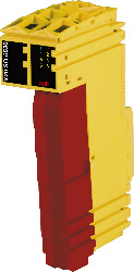
Número do material:
X20SO6530Descrição:
- 6 safe relay outputs
- Output type "Relay"
- Relay module for 230 VAC / 24 VDC
- Switching current 6 A
- Normally open contact
- Single-channel isolated outputs
This module is equipped with 6 safe relay outputs.
The module can be used for controlling floating actuators in safety-related applications up to PL e or SIL 3.
Safety relays are installed in the module. The positively driven feedback contacts are evaluated internally by the module. Safe digital output channels provide protection against automatic restart when network errors occur.
This module is designed for X20 12-pin terminal blocks.
Acessórios obrigatórios
| Atualizações de HW Automation Studio | Version (Data) | Download |
|---|---|---|
| V4.0 HW Upgrade (X20SO6530) | EXE / 2 MB | |
| V4.6 HW Upgrade (X20SO6530) | EXE / 2 MB | |
| V6.0 HW Upgrade (X20SO6530) | EXE / 485 KB |
| Documentação | Version (Data) | Download |
|---|---|---|
| Data sheets SafeIO and SafeLogic | PDF / 29 MB | |
| Integrated safety technology user's manual | PDF / 59 MB | |
| X20 Package leaflet ATEX/CSA | PDF / 2 MB | |
| X20 System User´s Manual | PDF / 49 MB |
| E-CAD (Modelos Electro ou EPLAN) | Version (Data) | Download |
|---|---|---|
| Makro-/Artikeldaten 4.0.1 (X20SO6530) | EXE / 698 KB | |
| X20 EPLAN P8 from V2.4 | EXE / 160 MB |
| Ferramentas / Utilitários / Exemplos | Version (Data) | Download |
|---|---|---|
| Sistema (VDMA) library | ZIP / 5 KB |
| M-CAD (Mechan. Modelos) | Version (Data) | Download |
|---|---|---|
| 3D file STEP X20Sxxx - Terminal block left side | ZIP / 19 KB | |
| DFX File I/O Slice | ZIP / 4 KB | |
| Dimensions PDF X20 I/O Slice | PDF / 45 KB |