Short description
| I/O module | 8 safe type A digital inputs, 4 pulse outputs, 24 VDC, 4 safe type A digital outputs, 24 VDC, 3 A, OSSD <500 µs, 2 safe type B2 digital outputs, 24 VDC, 50 mA, OSSD <500 µs, SafeLOGIC-X technology |
General information
Safety characteristics
| Note | See section "Safety characteristics". |
Limit values for SafeDESIGNER application
I/O power supply
| Nominal voltage | 24 VDC |
| Voltage range | 24 VDC -15% / +20% |
| Integrated protective function | Reverse polarity protection |
Safe digital inputs
Safe digital HS-LS outputs
Safe digital HS-HS outputs
| Quantity | 2 |
| Variant | FET, 2x positive switching, type B2, output level readable |
| Nominal voltage | 24 VDC |
| Nominal output current | 50 mA |
| Total nominal current | 100 mA |
| Output protection | See section "Inrush current behavior for output channels". |
| Braking voltage when switching off inductive loads | Max. 45 VDC |
| Error detection time | 1 s |
| Insulation voltage between channel and bus | 500 Veff |
| Peak short-circuit current | See section "Inrush current behavior for output channels". |
| Leakage current when the output is switched off | <1 mA |
| RDS(on) | 35 Ω |
| Switching voltage | I/O power supply minus voltage drop due to RDS(on) |
| Max. switching frequency | See section "Inrush current behavior for output channels". |
| Test pulse length | Max. 500 µs |
| Max. capacitive load | 100 nF |
Pulse outputs
Operating conditions
| Mounting orientation | |
| Horizontal | Yes |
| Vertical | Yes |
| Installation elevation above sea level | 0 to 2000 m, no limitation |
| Degree of protection per EN 60529 | IP20 |
Ambient conditions
| Temperature | |
| Operation | |
| Horizontal mounting orientation | 0 to 60°C |
| Vertical mounting orientation | 0 to 50°C |
| Derating | See section "Derating". |
| Storage | -40 to 85°C |
| Transport | -40 to 85°C |
| Relative humidity | |
| Operation | 5 to 95%, non-condensing |
| Storage | 5 to 95%, non-condensing |
| Transport | 5 to 95%, non-condensing |
Mechanical properties
| Note |
Order 2x safety-keyed terminal block separately. Order 1x safety-keyed bus module separately. |
| Pitch | 25+0.2 mm |
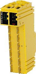
Número do material:
X20SLX842Descrição:
- openSAFETY manager for up to 10 SafeNODEs
- Flexibly programmable using Automation Studio / SafeDESIGNER
- Innovative management of safe machine options (SafeOPTION)
- Parameter and configuration management
- 8 safe digital inputs, sink circuit
- 4 pulse outputs
- Software input filter configurable for each channel
- 4 safe digital outputs, output type A with 3 A, source circuit
- 2 safe digital outputs, output type B with 50 mA, source circuit
- Integrated output protection
The module is equipped with SafeLOGIC functionality that allows it to safely execute applications designed in SafeDESIGNER. The module can be used in safety-related applications up to PL e or SIL 3.
In addition, the module coordinates the safety-related communication of all modules involved in the application. In this context, the module also monitors the configuration of these modules and carries out autonomous parameter downloads to the modules whenever necessary. This guarantees a consistent and correct module configuration in the network from a safety standpoint in all scenarios involving module replacement and service. These services are performed in conjunction with Automation Runtime on the standard CPU.
In addition, SafeLOGIC-X products have the same I/O properties as the associated SafeIO products (X20SC0xxx).
Acessórios obrigatórios
| Atualizações de HW Automation Studio | Version (Data) | Download |
|---|---|---|
| V4.1 HW Upgrade (X20SLX842) | EXE / 6 MB | |
| V4.2 HW Upgrade (X20SLX842) | EXE / 7 MB | |
| V4.6 HW Upgrade (X20SLX842) | EXE / 6 MB | |
| V6.0 HW Upgrade (X20SLX842) | EXE / 6 MB |
| Documentação | Version (Data) | Download |
|---|---|---|
| Data sheets SafeIO and SafeLogic | PDF / 29 MB | |
| Information sheet SafeLOGIC | PDF / 553 KB | |
| Integrated safety technology user's manual | PDF / 59 MB | |
| X20 System User´s Manual | PDF / 49 MB |
| E-CAD (Modelos Electro ou EPLAN) | Version (Data) | Download |
|---|---|---|
| X20 EPLAN P8 from V2.4 | EXE / 160 MB |
| Ferramentas / Utilitários / Exemplos | Version (Data) | Download |
|---|---|---|
| Sistema (VDMA) library | ZIP / 5 KB |
| M-CAD (Mechan. Modelos) | Version (Data) | Download |
|---|---|---|
| 3D file STEP/DXF X20(c)Sxxxxx | ZIP / 1 MB |