General information
| Certifications | |
| CE | Yes |
| UKCA | Yes |
| CRA (Cyber Resilience Act) | In preparation |
| UL |
cULus E225616 Power conversion equipment |
Motor power
| Specified on nameplate | 0.37 kW (0.5 HP) |
Mains connection
Line-conducted and radiated emissions
| With integrated filter | |
|
Motor cable length per IEC/EN 61800-3 Cat. C2 environment 1 (public power network) |
10 m |
|
Motor cable length per IEC/EN 61800-3 Cat. C3 environment 2 (industrial power system) |
10 m |
| With add-on filter | |
|
Motor cable length per IEC/EN 61800-3 Cat. C1 environment 1 (public power network) |
20 m |
|
Motor cable length per IEC/EN 61800-3 Cat. C2 environment 1 (public power network) |
50 m |
|
Motor cable length per IEC/EN 61800-3 Cat. C3 environment 2 (industrial power system) |
100 m |
| With add-on filter | 8I0FS009.200-2 |
Motor connection
Brake chopper
| Integrated dynamic brake transistors | Yes |
| Min. resistance value (external) | 40 Ω |
24 VDC power supply
| Input voltage | 24 VDC (-15%/+20%) |
| Current | Max. 1.1 A |
Available internal power supplies
| Output voltage 24 VDC | |
| Max. output current at 24 VDC | 100 mA |
| Output voltage 10 VDC | |
| Max. output current at 10 VDC | 10 mA |
| Output voltage 24 VDC | 24 VDC (-15%/+20%) |
| Output voltage 10 VDC | 10 VDC (-0%/+10%) |
Digital inputs
Safe input - STO (Safe Torque Off)
| Input impedance | |
| Current consumption | 16 mA |
| Electrical isolation | |
| Input - ACOPOSinverter | Yes |
| Input - Input | No |
| Quantity | 1 |
| Nominal voltage | 24 VDC (max. 30 VDC) |
| Input impedance | 1.5 kΩ |
Analog inputs
| Electrical isolation | |
| Input - Input | No |
| Input - ACOPOSinverter | Yes |
| Input | |
| Voltage |
AI1: 0 to 10 VDC AI2: 0 ±10 VDC, max. 30 VDC |
| Current | 0 to 20 mA (or 4 to 20 mA) |
| Input impedance | |
| Voltage | 30 kΩ |
| Current | 250 Ω |
| Quantity | 3 |
| Nonlinearity | ±0.2%, max. ±0.5% |
| Basic accuracy |
At 25°C: ±0.5% At -10 to 60°C: ±0.7% |
| Resolution | 10-bit |
| Sampling time | 2 ms |
Digital outputs
| Quantity | 1 |
| Nominal voltage | 24 VDC -15%/+20% |
| Max. voltage | 30 VDC |
| Output circuit | Source or sink |
| Sampling time | 2 ms |
| Max. current | 100 mA |
Relay outputs
| Execution | |
| Relay 1 | 1 changeover contact |
| Relay 2 | 1 normally open contact |
| Electrical isolation | |
| Output - ACOPOSinverter | Yes |
| Output - Output | No |
| Quantity | 2 |
| Nominal voltage | 30 VDC / 250 VAC |
| Switching current range |
Min. switching current: 5 mA at 24 VDC Max. switching current: R1 at cos φ = 1: 3 A at 250 VAC / 4 A at 30 VDC R2 at cos φ = 1: 5 A R1 and R2 at cos φ = 0.4: 2 A |
| Response time (max.) | 2 ms |
Analog outputs
| Electrical isolation | |
| Output - ACOPOSinverter | Yes |
| Output - Output | No |
| Max. load impedance | |
| Voltage | 470 Ω |
| Current | 800 Ω |
| Quantity | 1 |
| Output | 0 to 10 V or 0 to 20 mA |
| Nonlinearity | ±0.3% |
| Basic accuracy |
At 25°C: ±1% At -10 to 60°C: ±2% |
| Update time | 2 ms |
| Resolution | 10-bit |
Electrical properties
| Energy efficiency (IE classification) | |
| Power dissipation relative to continuous apparent power |
IE2 (10; 25): 1.8% (1x 200 VAC); 1.2% (1x 240 VAC) IE2 (50; 25): 1.6% (1x 200 VAC); 1% (1x 240 VAC) IE2 (10; 50): 1.8% (1x 200 VAC); 1.4% (1x 240 VAC) IE2 (50; 50): 1.7% (1x 200 VAC); 1.3% (1x 240 VAC) IE2 (90; 50): 1.8% (1x 200 VAC); 1.4% (1x 240 VAC) IE2 (10; 100): 2.4% (1x 200 VAC); 2% (1x 240 VAC) IE2 (50; 100): 2.2% (1x 200 VAC); 1.9% (1x 240 VAC) IE2 (90; 100): 2.5% (1x 200 VAC); 2% (1x 240 VAC) |
| Nominal losses in standby mode | 6 W |
Operating conditions
Ambient conditions
| Temperature | |
| Operation |
-10 to 50°C without derating 50 to 60°C with derating |
| Storage | -25 to 70°C |
| Max. vibration resistance |
1 gn 13 to 200 Hz EN/IEC 60068-2-6 1.5 mm peak to peak 2 to 13 Hz EN/IEC 60068-2-6 |
Mechanical properties
| Dimensions | |
| Width | 72 mm |
| Height | 188 mm |
| Height without shield plate | 143 mm |
| Depth | 128 mm |
| Weight | 1 kg |
Materiaalnummer:
8I66S200037.00-000Omschrijving:
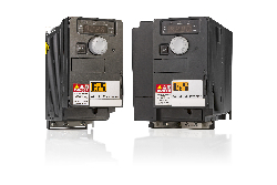
Base device for ACOPOSinverter P66 and P64new, 1 x 200 to 240 V, 0.37 kW, integrated EMC filter and brake chopper, shield plate included in delivery
Order number - ACOPOSinverter P66:
8I66S200037.0P-000: Inverter with POWERLINK communication card
8I66S200037.0X-000: Inverter with X2X Link communication card
8I66S200037.0C-000: Inverter with integrated CANopen interface
Order number - ACOPOSinverter P64new:
8I64S200037.0X-000: Inverter with X2X Link communication card
Bij de levering inbegrepen
Optional EMC kit
| 8I0XE066.401-1 | Base device for ACOPOSinverter P66 and P64new, 1x 200 to 240 V, 0.37 kW, integrated EMC filter and brake chopper, shield plate included in delivery |
Optionele toebehoren
Cable and adapters
| 8I0XC001.003-1 | Base device for ACOPOSinverter P66 and P64new, 1x 200 to 240 V, 0.37 kW, integrated EMC filter and brake chopper, shield plate included in delivery |
| 8I0XD304.301-1 | Base device for ACOPOSinverter P66 and P64new, 1x 200 to 240 V, 0.37 kW, integrated EMC filter and brake chopper, shield plate included in delivery |
| 8I0XD304.303-1 | Base device for ACOPOSinverter P66 and P64new, 1x 200 to 240 V, 0.37 kW, integrated EMC filter and brake chopper, shield plate included in delivery |
| 8I0XD304.305-1 | Base device for ACOPOSinverter P66 and P64new, 1x 200 to 240 V, 0.37 kW, integrated EMC filter and brake chopper, shield plate included in delivery |
| 8I0XD304.310-1 | Base device for ACOPOSinverter P66 and P64new, 1x 200 to 240 V, 0.37 kW, integrated EMC filter and brake chopper, shield plate included in delivery |
Cable and adapters (CANopen)
| 8I0CA001.000-1 | Base device for ACOPOSinverter P66 and P64new, 1x 200 to 240 V, 0.37 kW, integrated EMC filter and brake chopper, shield plate included in delivery |
| 8I0XT001.000-1 | Base device for ACOPOSinverter P66 and P64new, 1x 200 to 240 V, 0.37 kW, integrated EMC filter and brake chopper, shield plate included in delivery |
Graphic display
| 8I0XD301.300-1 | Base device for ACOPOSinverter P66 and P64new, 1x 200 to 240 V, 0.37 kW, integrated EMC filter and brake chopper, shield plate included in delivery |
| 8I0XD302.300-1 | Base device for ACOPOSinverter P66 and P64new, 1x 200 to 240 V, 0.37 kW, integrated EMC filter and brake chopper, shield plate included in delivery |
| 8I0XD303.300-1 | Base device for ACOPOSinverter P66 and P64new, 1x 200 to 240 V, 0.37 kW, integrated EMC filter and brake chopper, shield plate included in delivery |
| 8I0XD305.300-1 | Base device for ACOPOSinverter P66 and P64new, 1x 200 to 240 V, 0.37 kW, integrated EMC filter and brake chopper, shield plate included in delivery |
Optional EMC filters
| 8I0FS009.200-2 | Base device for ACOPOSinverter P66 and P64new, 1x 200 to 240 V, 0.37 kW, integrated EMC filter and brake chopper, shield plate included in delivery |
Optional braking resistors
| 8I0BR100.000-1 | Base device for ACOPOSinverter P66 and P64new, 1x 200 to 240 V, 0.37 kW, integrated EMC filter and brake chopper, shield plate included in delivery |
Optional line chokes
| 8I0CS004.000-1 | Base device for ACOPOSinverter P66 and P64new, 1x 200 to 240 V, 0.37 kW, integrated EMC filter and brake chopper, shield plate included in delivery |
Terminal blocks
| 8TB2104.2010-00 | Base device for ACOPOSinverter P66 and P64new, 1x 200 to 240 V, 0.37 kW, integrated EMC filter and brake chopper, shield plate included in delivery |
| 8TB2104.2210-00 | Base device for ACOPOSinverter P66 and P64new, 1x 200 to 240 V, 0.37 kW, integrated EMC filter and brake chopper, shield plate included in delivery |
| 8TB2108.2010-00 | Base device for ACOPOSinverter P66 and P64new, 1x 200 to 240 V, 0.37 kW, integrated EMC filter and brake chopper, shield plate included in delivery |
| 8TB2108.2210-00 | Base device for ACOPOSinverter P66 and P64new, 1x 200 to 240 V, 0.37 kW, integrated EMC filter and brake chopper, shield plate included in delivery |
X2X Link Cable
| X67CA0X99.1000 | Base device for ACOPOSinverter P66 and P64new, 1x 200 to 240 V, 0.37 kW, integrated EMC filter and brake chopper, shield plate included in delivery |
| X67CA0X99.5000 | Base device for ACOPOSinverter P66 and P64new, 1x 200 to 240 V, 0.37 kW, integrated EMC filter and brake chopper, shield plate included in delivery |
| Algemeen | Versie (Datum) | Download |
|---|---|---|
| ACPi SafeConfigurator | Login voor downloaden |
| Bestanden met beschrijvingen van veldbusapparatuur | Versie (Datum) | Download |
|---|---|---|
| ACOPOSinverter P66 EDS Package | ZIP / 37 KB |
| Certificaten | Versie (Datum) | Download |
|---|---|---|
| Certificate ACOPOSinverter P66/P74/P76 Safety | PDF / 576 KB | |
| E225616 UL Certificate of Compliance ACOPOSinverter_Px6_Px4 | PDF / 321 KB |
| Documentatie | Versie (Datum) | Download |
|---|---|---|
| ACOPOSinverter P64new User's Manual | PDF / 2 MB | |
| ACOPOSinverter P66 User's Manual | PDF / 24 MB | |
| Safety Data Sheet ACPi P66 P76 | PDF / 759 KB |
| E-CAD (Electro of EPLAN Templates) | Versie (Datum) | Download |
|---|---|---|
| ACOPOSinverter EPLAN P8 from 2.4 | EXE / 84 MB |
| M-CAD (Mechan. Templates) | Versie (Datum) | Download |
|---|---|---|
| ACOPOSinverter P66 CAD 2D 3D | ZIP / 15 MB |
| Tools / Hulpprogramma's / Voorbeelden | Versie (Datum) | Download |
|---|---|---|
| Sistema (VDMA) library | ZIP / 5 KB |