Short description
| I/O module | 4 digital outputs 250 VDC / 240 VAC, outputs single-channel isolated |
General information
Digital outputs
Electrical properties
| Electrical isolation | Channel isolated from channel, bus and I/O power supply |
Operating conditions
Ambient conditions
| Temperature | |
| Operation | |
| Horizontal mounting orientation | -25 to 60°C |
| Vertical mounting orientation | -25 to 50°C |
| Derating | - |
| Storage | -40 to 85°C |
| Transport | -40 to 85°C |
| Relative humidity | |
| Operation | 5 to 95%, non-condensing |
| Storage | 5 to 95%, non-condensing |
| Transport | 5 to 95%, non-condensing |
Mechanical properties
| Note |
Order 1x terminal block X20TB32 separately. Order 1x bus module X20BM32 separately. |
| Pitch | 25+0.2 mm |
Référence produit:
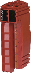
X20DO4F49Description:
- 4 digital outputs
- Relay module for 250 VDC / 240 VAC
- 2 normally open contacts and 2 changeover contacts
- Single-channel isolated outputs
This module is equipped with 4 relay outputs (2 normally open and 2 changeover contacts each) for 250 VDC / 240 VAC. The outputs are single-channel isolated.
Accessoires obligatoires
| Automation Studio HW Upgrades | Version (date) | Téléchargement |
|---|---|---|
| V4.0 HW Upgrade (X20DO4F49) | EXE / 889 Ko | |
| V6.0 HW Upgrade (X20DO4F49) | EXE / 574 Ko |
| Documentation | Version (date) | Téléchargement |
|---|---|---|
| Data sheet X20DO4F49 | PDF / 774 Ko | |
| X20 System User´s Manual | PDF / 49 Mo |
| E-CAD (modèles Electro ou EPLAN) | Version (date) | Téléchargement |
|---|---|---|
| X20 EPLAN P8 from V2.4 | EXE / 160 Mo |