Short description
| I/O module | Ultrasonic path measurement module, 2 path measurement rods, 4 path recorders, speed measurement |
General information
| Diagnostics | |
| Module run/error | Yes, using LED status indicator and software |
| Power consumption | |
| Bus | 0.01 W |
| Internal I/O | 1.1 W |
| Certifications | |
| CE | Yes |
| UKCA | Yes |
| CRA (Cyber Resilience Act) | In preparation |
| ATEX |
Zone 2, II 3G Ex nA nC IIA T5 Gc IP20, Ta (see X20 user's manual) FTZÚ 09 ATEX 0083X |
| UL |
cULus E115267 Industrial control equipment |
| HazLoc |
cCSAus 244665 Process control equipment for hazardous locations Class I, Division 2, Groups ABCD, T5 |
| KC | Yes |
| B&R ID code | 0x2188 |
| Status indicators | I/O function per channel, operating state, module status |
| Additional power dissipation caused by actuators (resistive) [W] | - |
Channels for path and speed measurements
| Encoder power supply | |
| Voltage | 24 VDC, module-internal, max. 150 mA |
| Monitoring | Configurable overvoltage/undervoltage monitoring (±10%, ±15%, ±20%, ±25%) |
| Short-circuit proof | Rev. D0 and later |
| Inputs | |
| Path measurement | Resolution = 0.01 mm, measurement range = ±5.2 m |
| Speed measurement | Resolution = 0.1 mm/s, measurement range = ±3.2 m/s |
| Accuracy | ±50 ppm ±5 ppm/year |
| Short-circuit protection | No |
| Quantity | 2 |
| Supported encoder types |
Start/Stop interface EP start/stop interface DPI/IP interface |
| Input and output level | RS422 differential level |
| Multi-magnet measurement | Yes, in combination per rod, max. 4 magnets total |
| Outputs | 1.6 µs durational initialization pulse |
Electrical properties
| Electrical isolation |
Channel isolated from bus Channel not isolated from channel
|
Operating conditions
| Mounting orientation | |
| Horizontal | Yes |
| Vertical | Yes |
| Installation elevation above sea level | |
| 0 to 2000 m | No limitation |
| >2000 m | Reduction of ambient temperature by 0.5°C per 100 m |
| Degree of protection per EN 60529 | IP20 |
Ambient conditions
| Temperature | |
| Operation | |
| Horizontal mounting orientation | -25 to 60°C |
| Vertical mounting orientation | -25 to 50°C |
| Derating | - |
| Storage | -40 to 85°C |
| Transport | -40 to 85°C |
| Relative humidity | |
| Operation | 5 to 95%, non-condensing |
| Storage | 5 to 95%, non-condensing |
| Transport | 5 to 95%, non-condensing |
Mechanical properties
| Note |
Order 1x terminal block X20TB12 separately. Order 1x bus module X20BM11 separately. |
| Pitch | 12.5+0.2 mm |
Référence produit:
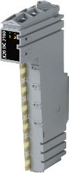
X20DC2190Description:
- Ultrasonic transducer module
- Path measurement (resolution 10 µm)
- Speed measurement (resolution 100 µm/s)
- 1, 2, 3 and 4 magnetic rod measurements possible
- DPI/IP protocol supported
This module can be used to determine paths and to calculate speeds at the same time. The ultrasonic transducer rods are connected directly to the RS422 interface. Communication to the transducer rod takes place using start/stop signals. With the DPI/IP protocol, it is also possible, for example, to read operational properties directly from the transducer. During service (when a transducer is being exchanged) the machine can be started again quickly without additional configuration work.
The module is designed for connecting 2 transducer rods with a total of up to 4 paths. That means, for example, that 2 ultrasonic transducers with 2 magnets each or one with 4 magnets can be used. The combination 3/1 is also possible. The module provides 24 VDC as an external supply for the sensor.
Accessoires obligatoires
| Automation Studio HW Upgrades | Version (date) | Téléchargement |
|---|---|---|
| V2.6 HW Upgrade (X20DC2190) | EXE / 1 Mo | |
| V3.0 HW Upgrade (X20DC2190) | EXE / 1 Mo | |
| V4.0 HW Upgrade (X20DC2190) | EXE / 1 Mo |
| Documentation | Version (date) | Téléchargement |
|---|---|---|
| Datasheet X20(c)DC2190 | PDF / 880 Ko | |
| X20 Package leaflet ATEX/CSA | PDF / 2 Mo | |
| X20 System User´s Manual | PDF / 49 Mo |
| E-CAD (modèles Electro ou EPLAN) | Version (date) | Téléchargement |
|---|---|---|
| X20 EPLAN P8 from V2.4 | EXE / 160 Mo |
| M-CAD (modèles mécaniques) | Version (date) | Téléchargement |
|---|---|---|
| 3D File DXF/STEP X20 Electronic module | ZIP / 10 Ko | |
| 3D File STEP X20 I/O-Slice | ZIP / 872 Ko | |
| Dimensions PDF X20 Electronic module | PDF / 3 Ko |