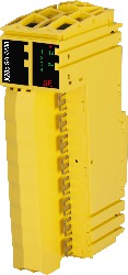
Short description
I/O module 2x 2 safe type A analog inputs, 0.5 to 25 mA, channels individually galvanically isolated
General information
B&R ID code 0xDD9F
System requirements
Automation Studio 4.0.16 or later
Automation Runtime V3.08 or later
SafeDESIGNER 3.1.0 or later
Safety Release 1.7 or later
mapp Technology Package mapp Safety 5.7.0 or later
Status indicators I/O function per channel, operating state, module status
Diagnostics
Module run/error Yes, using LED status indicator and software
Inputs Yes, using LED status indicator and software
Blackout mode
Scope Module
Function Module functionality
Standalone mode No
Max. I/O cycle time 2 ms
Power consumption
Bus 0.25 W
Internal I/O 1.7 W
Additional power dissipation caused by actuators (resistive) [W] 0.36
Electrical isolation
Channel - Bus Yes
Channel - Channel Yes
Channel pair - Channel pair Yes
Certifications
CE Yes
UKCA Yes
Functional safety cULus FSPC E361559
Energy and industrial systems
Certified for functional safety
ANSI UL 1998:2013
Functional safety IEC 61508:2010, SIL 3
EN 62061:2005/A2:2015, SIL 3
EN ISO 13849-1:2015, Cat. 4 / PL e
IEC 61511:2004, SIL 3
Functional safety EN 50156-1:2004
ATEX Zone 2, II 3G Ex nA nC IIA T5 Gc
IP20, Ta (see X20 user's manual)
FTZÚ 09 ATEX 0083X
UL cULus E115267
Industrial control equipment
HazLoc cCSAus 244665
Process control equipment
for hazardous locations
Class I, Division 2, Groups ABCD, T5
DNV Temperature: A (0 to 45°C)
Humidity: B (up to 100%)
Vibration: A (0.7 g)
EMC: B (bridge and open deck)
LR ENV1
KR Yes
ABS Yes
BV EC21B
Temperature: 5 - 45°C
Vibration: 0.7 g
EMC: Bridge and open deck
Safety characteristics
Note The following characteristic values apply only to the use of input channel pairs.
Assessing the channels from a safety point of view when they are used individually is not possible.
EN ISO 13849-1:2015
Category Cat. 4 (SHUNTTEST enabled), Cat. 3 (SHUNTTEST disabled)
PL PL e (SHUNTTEST enabled), PL d (SHUNTTEST disabled)
DC >94% (regardless of whether SHUNTTEST is enabled or disabled)
MTTFD per channel 2200 years (regardless of whether SHUNTTEST is enabled or disabled)
Mission time Max. 20 years
IEC 61508:2010,
IEC 61511:2004,
EN 62061:2013
SIL CL SIL 3 (regardless of whether SHUNTTEST is enabled or disabled)
SFF >90% (regardless of whether SHUNTTEST is enabled or disabled)
PFH / PFHd per channel <1*10-9 (regardless of whether SHUNTTEST is enabled or disabled)
PFH / PFHd
openSAFETY wired Negligible
openSAFETY wireless <1*10-14 * Number of openSAFETY packets per hour
PFD per channel <1*10-4 (regardless of whether SHUNTTEST is enabled or disabled)
Proof test interval (PT) 20 years
I/O power supply
Nominal voltage 24 VDC
Voltage range 24 VDC -15% / +20%
Safe analog inputs
Quantity 2 safe input channel pairs
Variant Type A
Input type Differential input
Digital converter resolution 24-bit
Conversion time See chapter "I/O update time".
Output format SAFEINT
Load Up to hardware revision D3: 230 to 420 Ω, hardware revision E0 or later: 185 to 245 Ω
Input protection Protection against external supply voltages and overcurrent
Open-circuit detection Yes, using software
Permissible input signal
Voltage Max. 30.5 V
Conversion procedure Sigma-delta
Max. error at 25°C
Gain
0.5 to <4 mA <0.3%
4 to 25 mA <0.08%
Offset
0.5 to <4 mA <2 µA
4 to 25 mA <6.3 µA
Max. gain drift
0.5 to <4 mA <1.225 µA/°C
4 to 25 mA <1.225 µA/°C
Max. offset drift
0.5 to <4 mA <0.735 µA/°C
4 to 25 mA <0.735 µA/°C
Common-mode rejection
DC >70 dB
50 Hz >70 dB
Common-mode range Between the inputs ±50 V
Nonlinearity <0.003%
Measurement range 0.5 to 25 mA
Input filter
Hardware First-order low-pass filter / cutoff frequency 500 Hz
Software Sinc3 filter
Resolution 1 µA/LSB
Overload detection Yes, using software
Test voltage
Channel - Bus 500 VDC
Channel pair - Channel pair 500 VDC
Channel - Ground 500 VDC
Safety-related accuracy per channel
Cat. 3 0.184 mA
Cat. 4 0.49 mA
Filter time Configurable between 1 and 66.7 ms
Sensor power supply
Nominal voltage 29 VDC ±5%
Nominal output current Max. 60 mA
Short-circuit proof Yes, continuous
Electrical isolation
Sensor power supply - Channel No
Sensor power supply - Sensor power supply Yes
RDS(on) 50 Ω
Behavior on short circuit Voltage cutoff
Operating conditions
Mounting orientation
Horizontal Yes
Vertical Yes
Installation elevation above sea level 0 to 2000 m, no limitation
Degree of protection per EN 60529 IP20
Ambient conditions
Temperature
Operation
Horizontal mounting orientation -25 to 60°C
Vertical mounting orientation -25 to 40°C
Derating See section "Derating".
Starting temperature Yes, -40°C
Storage -40 to 85°C
Transport -40 to 85°C
Relative humidity
Operation Up to 100%, condensing
Storage 5 to 95%, non-condensing
Transport 5 to 95%, non-condensing
Mechanical properties
Note Order 1x safety-keyed terminal block separately.
Order 1x safety-keyed bus module separately.
Pitch 25+0.2 mm
Número de material:
X20cSA4430
Descripción:
  • 2 safe analog input pairs for current measurement 0.5 to 25 mA
  • 24-bit digital converter resolution
  • Channels individually galvanically isolated
  • Sensor power supplies galvanically isolated
  • Input filter configurable

The module is equipped with 2 safe analog input pairs for current measurement. Each input pair has its own sensor power supply. The channels with their respective sensor supplies are electrically isolated from each other. It can be used to capture current signals in the range from 0.5 to 25 mA.

The safe analog input module is suitable for safely acquiring current signals for safety-related applications up to PL e or SIL 3.

This module is designed for X20 16-pin terminal blocks.

Accesorios obligatorios
Bus modules
X20cBM33 X20 bus module, coated, for X20 SafeIO modules, internal I/O power supply connected through
Terminal blocks
X20TB5F X20 terminal block, 16-pin, safety-keyed
Actualizaciones de hardware de Automation Studio Versión (fecha) Descargar
V4.0 HW Upgrade (X20cSA4430) EXE / 2 MB
V4.6 HW Upgrade (X20cSA4430) EXE / 934 KB
Certificados Versión (fecha) Descargar
244665 CSA HazLoc CoC X20, X67 PDF / 158 KB
ABS Certificate of Product Design Assessment - X20 IO Series PDF / 2 MB
BV Type Approval Certificate - X20 PDF / 556 KB
DNV Type Approval Certificate - X20 PDF / 194 KB
E115267 UL CoC X20 PDF / 1 MB
EU Declaration FS PLC X20 PDF / 210 KB
FS Certificate SafeDESIGNER, SafeLOGIC, SafeIO PDF / 880 KB
FS Certificate mapp Safety PDF / 974 KB
FTZU 09 ATEX 0083X PDF / 771 KB
KR Type Approval Certificate MIL39390-AC003 (X20 System) PDF / 758 KB
Lloyds Register PDF / 502 KB
RINA Type Approval Certificate - X20 / Power Panel T30 PDF / 1 MB
UK Declaration FS PLC X20 PDF / 112 KB
Documentación Versión (fecha) Descargar
Data sheet X20(c)SA4430 - Legacy PDF / 1,002 KB
Data sheet X20(c)SA4430 - mapp Safety PDF / 599 KB
Installation- / EMC-Guide PDF / 20 MB
X20 System User´s Manual PDF / 7 MB
E-CAD (plantillas Electro o EPLAN) Versión (fecha) Descargar
X20 EPLAN P8 from V2.4 EXE / 160 MB
M-CAD (plantillas mecánicas) Versión (fecha) Descargar
3D file STEP X20(c)Sxxxxx - Terminal block right side ZIP / 21 KB

Seleccione país e idioma

B&R Logo