Short description
| I/O module | 8 digital inputs 24 VDC for 1-wire connections, 4 digital outputs 24 VDC for 1-wire connections |
General information
Digital inputs
| Input characteristics per EN 61131-2 | Type 1 |
| Input voltage | 24 VDC -15% / +20% |
| Input current at 24 VDC | Typ. 3.75 mA |
| Input circuit | Sink |
| Input filter | |
| Hardware | ≤100 µs |
| Software | Default 1 ms, configurable between 0 and 25 ms in 0.2 ms increments |
| Connection type | 1-wire connections |
| Input resistance | Typ. 6.4 kΩ |
| Switching threshold | |
| Low | <5 VDC |
| High | >15 VDC |
| Insulation voltage between channel and bus | 500 Veff |
Digital outputs
| Variant | Current-sourcing FET |
| Switching voltage | 24 VDC -15% / +20% |
| Nominal output current | 0.5 A |
| Total nominal current | 2 A |
| Connection type | 1-wire connections |
| Output circuit | Source |
| Output protection |
Thermal shutdown in the event of overcurrent or short circuit (see value "Short-circuit peak current") Internal freewheeling diode for switching inductive loads (see section "Switching inductive loads") |
| Diagnostic status | Output monitoring with 10 ms delay |
| Leakage current when the output is switched off | 5 µA |
| RDS(on) | 210 mΩ |
| Peak short-circuit current | <12 A |
| Switch-on in the event of overload shutdown or short-circuit shutdown | Approx. 10 ms (depends on the module temperature) |
| Switching delay | |
| 0 → 1 | <300 µs |
| 1 → 0 | <300 µs |
| Switching frequency | |
| Resistive load | Max. 500 Hz |
| Inductive load | See section "Switching inductive loads". |
| Braking voltage when switching off inductive loads | Typ. 50 VDC |
| Insulation voltage between channel and bus | 500 Veff |
Electrical properties
| Electrical isolation |
Channel isolated from bus Channel not isolated from channel |
Operating conditions
| Mounting orientation | |
| Horizontal | Yes |
| Vertical | Yes |
| Installation elevation above sea level | |
| 0 to 2000 m | No limitation |
| >2000 m | Reduction of ambient temperature by 0.5°C per 100 m |
| Degree of protection per EN 60529 | IP20 |
Ambient conditions
| Temperature | |
| Operation | |
| Horizontal mounting orientation | -25 to 60°C |
| Vertical mounting orientation | -25 to 50°C |
| Derating | - |
| Storage | -40 to 85°C |
| Transport | -40 to 85°C |
| Relative humidity | |
| Operation | Up to 100%, condensing |
| Storage | 5 to 95%, non-condensing |
| Transport | 5 to 95%, non-condensing |
Mechanical properties
| Note |
Order 1x terminal block X20TB12 separately. Order 1x bus module X20cBM11 separately. |
| Pitch | 12.5+0.2 mm |
Material number:
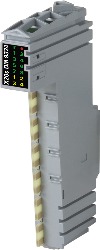
X20cDM9324Description:
- 8 digital inputs, sink connections
- 4 digital outputs, source connections
- 1-wire connections
- Configurable software input filter for entire module
- Integrated output protection
This module is equipped with 8 inputs and 4 outputs for 1-wire connections. The inputs are designed for sink connections, the outputs for source connections.
Mandatory Accessories
| Automation Studio HW Upgrades | Version (Date) | Download |
|---|---|---|
| V3.0 HW Upgrade (X20cDM9324) | EXE / 2 MB | |
| V4.0 HW Upgrade (X20cDM9324) | EXE / 779 KB |
| Documentation | Version (Date) | Download |
|---|---|---|
| Coated modules | PDF / 62 KB | |
| Data sheet X20(c)DM9324 | PDF / 439 KB | |
| X20 Package leaflet ATEX/CSA | PDF / 2 MB | |
| X20 System User´s Manual | PDF / 49 MB |
| E-CAD (Electro or EPLAN Templates) | Version (Date) | Download |
|---|---|---|
| X20 EPLAN P8 from V2.4 | EXE / 160 MB |
| M-CAD (Mechan. Templates) | Version (Date) | Download |
|---|---|---|
| 3D File DXF/STEP X20 Electronic module | ZIP / 10 KB | |
| 3D File STEP X20 I/O-Slice | ZIP / 872 KB | |
| Dimensions PDF X20 Electronic module | PDF / 3 KB |