Short description
| I/O module | 4 digital inputs, 2 digital outputs, 1 input for full-bridge strain gauge |
General information
| B&R ID code | 0x1CDF |
| Status indicators | I/O function per channel, supply voltage, bus function |
| Diagnostics | |
| Outputs | Yes, using LED status indicator |
| I/O power supply | Yes, using LED status indicator and software |
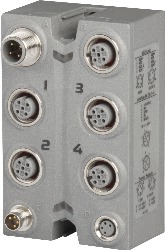
| Connection type | |
| X2X Link | M12, B-coded |
| Inputs/Outputs | 4x M12, A-coded |
| I/O power supply | M8, 4-pin |
| Power consumption | |
| Internal I/O | 1 W |
| X2X Link power supply | 0.75 W |
| Certifications | |
| CE | Yes |
| UKCA | Yes |
| CRA (Cyber Resilience Act) | In preparation |
| ATEX |
Zone 2, II 3G Ex nA IIA T5 Gc IP67, Ta = 0 - Max. 60°C TÜV 05 ATEX 7201X |
| UL |
cULus E115267 Industrial control equipment |
| HazLoc |
cCSAus 244665 Process control equipment for hazardous locations Class I, Division 2, Groups ABCD, T5 |
| KC | Yes |
I/O power supply
Strain gauge supply
| Voltage | 4.422 VDC / max. 60 mA |
| Voltage drop for short-circuit protection at 60 mA | Max. 0.36 VDC |
| Short-circuit proof | Yes |
Sensor/Actuator power supply
| Voltage | I/O power supply minus voltage drop for short-circuit protection |
| Voltage drop for short-circuit protection at 0.5 A | Max. 2 VDC |
| Summation current | Max. 0.5 A |
| Short-circuit proof | Yes |
Full-bridge strain gauge
| Strain gauge factor | ±15.625 to ±125 mV/V, configurable using software |
| Input type | Differential, used to evaluate a full-bridge strain gauge |
| Digital converter resolution | 24-bit |
| Conversion time | Depends on the configured data output rate |
| Data output rate | 10 to 3750 samples per second, configurable using software |
| Input filter | |
| Cutoff frequency | 50 kHz |
| Order | 1 |
| Slope | 20 dB |
| Operating range / Measurement sensor | 75 to 5000 Ω |
| Influence of cable length | Twisted and shielded conductors, cable length as short as possible, cable routing separate from load circuits, without intermediate terminal to sensor |
| Input protection | RC protection |
| Input current | 450 nA |
| Common-mode range |
0 to 3 VDC Permissible input voltage range (with regard to the electric potential strain gauge GND) on the inputs "Input +" and "Input -" |
| Insulation voltage between input and bus | 500 Veff |
| Gain | 1 to 8, configurable using software |
| Conversion procedure | Sigma-delta |
| Output of digital value | |
| Broken bridge supply line | Value approaching 0 |
| Broken sensor line | Value approaching ±final value |
| Valid range of values | 0x7FFF FFFF to 0x8000 0001 |
| Strain gauge supply | |
| Voltage | 4.5 VDC / max. 60 mA |
| Connection | 4-wire connections |
| Short-circuit and overload-proof | Yes |
| Quantization | |
| LSB value (16-bit) | |
| 69 mV/V | 9.31 µV |
| 138 mV/V | 18.6 µV |
| 276 mV/V | 37.3 µV |
| 553 mV/V | 74.6 µV |
| LSB value (24-bit) | |
| 69 mV/V | 36.4 nV |
| 138 mV/V | 72.8 nV |
| 276 mV/V | 146.0 nV |
| 553 mV/V | 251.0 nV |
| Temperature coefficient | 50 ppm/°C |
Digital inputs
| Quantity | 4 |
| Nominal voltage | 24 VDC |
| Input characteristics per EN 61131-2 | Type 1 |
| Input voltage | 24 VDC ±25% |
| Input current at 24 VDC | Typ. 5 mA |
| Input circuit | Sink |
| Input filter | |
| Hardware | <1 ms |
| Software | - |
| Input resistance | Typ. 4.27 kΩ |
| Sensor power supply | 0.5 A summation current |
| Switching threshold | |
| Low | <5 VDC |
| High | >15 VDC |
| Insulation voltage between channel and bus | 500 Veff |
Digital outputs
| Quantity | 2 |
| Nominal voltage | 24 VDC |
| Switching voltage | 24 VDC ±25% |
| Output circuit | Source |
| Output protection | Thermal shutdown in the event of overcurrent or short circuit, integrated protection for switching inductive loads, reverse polarity protection of the output power supply |
| Actuator power supply | External |
| Insulation voltage between output and bus | 500 Veff |
| Nominal output current | |
| Output 1 | 0.5 A |
| Output 2 | 1 A |
| Switch-on time of output driver | |
| Output 1 | |
| Typical | 50 µs |
| 0 → 1 (90% VOut) | Max. 100 µs |
| Output 2 | |
| Typical | 60 µs |
| 0 → 1 (90% VOut) | Max. 160 µs |
| Switch-off time of output driver | |
| Output 1 | |
| Typical | 75 µs |
| 1 → 0 (90% VOut) | Max. 150 µs |
| Output 2 | |
| Typical | 15 µs |
| 1 → 0 (90% VOut) | Max. 50 µs |
| Braking voltage when switching off inductive loads | |
| Output 1 | -47 VDC |
| Output 2 | Approx. 1 VDC |
| Max. frequency | |
| Output 1 | 100 Hz |
| Output 2 | 1 kHz |
Electrical properties
| Electrical isolation |
Channel isolated from bus and digital isolated from analog Digital not isolated from I/O power supply
|
Operating conditions
| Mounting orientation | |
| Any | Yes |
| Installation elevation above sea level | |
| 0 to 2000 m | No limitation |
| >2000 m | Reduction of ambient temperature by 0.5°C per 100 m |
| Degree of protection per EN 60529 | IP67 |
Ambient conditions
| Temperature | |
| Operation | -25 to 60°C |
| Storage | -40 to 85°C |
| Transport | -40 to 85°C |
Mechanical properties
| Dimensions | |
| Width | 53 mm |
| Height | 85 mm |
| Depth | 42 mm |
| Weight | 200 g |
| Torque for connections | |
| M8 | Max. 0.4 Nm |
| M12 | Max. 0.6 Nm |
Номер модель:
X67UM1352Описание:
- 1 strain gauge input with 24-bit resolution
- High data output rate (10 to 3,750 Hz)
- Adjustable gain
- 1 high-side output 24 VDC, 0.5 A
- 1 high-side output 24 VDC, 1.0 A
This module is used for the decentralized connection of a force sensor using strain gauge with a converter resolution up to 24 bits. The module is also equipped with 4 digital inputs and 2 digital outputs.
| E-CAD (Electro или EPLAN шаблоны) | Версия (Дата) | Загрузка |
|---|---|---|
| X67 EPLAN P8 from V2.4 | EXE / 105 МБ |
| M-CAD (Механические Шаблоны | Версия (Дата) | Загрузка |
|---|---|---|
| 3D File DXF/STEP X67 | ZIP / 2 МБ |
| Документация | Версия (Дата) | Загрузка |
|---|---|---|
| Datasheet X67UM1352 | PDF / 1 МБ | |
| X67 System User´s Manual | PDF / 19 МБ |
| Обновление Automation Studio HW | Версия (Дата) | Загрузка |
|---|---|---|
| V2.6 HW Upgrade (X67UM1352) | EXE / 1 МБ | |
| V3.0 HW Upgrade (X67UM1352) | EXE / 2 МБ | |
| V4.0 HW Upgrade (X67UM1352) | EXE / 1 МБ |