Short description
| Communication module | 1x POWERLINK (V1/V2) managing or controlled node |
General information
| B&R ID code | 0x1F1F |
| Status indicators | Module status, bus function |
| Diagnostics | |
| Module status | Yes, using LED status indicator and software |
| Bus function | Yes, using LED status indicator and software |
| Power consumption | 2 W |
| Additional power dissipation caused by actuators (resistive) [W] | - |
| Certifications | |
| CE | Yes |
| UKCA | Yes |
| ATEX |
Zone 2, II 3G Ex nA nC IIA T5 Gc IP20, Ta (see X20 user's manual) FTZÚ 09 ATEX 0083X |
| UL |
cULus E115267 Industrial control equipment |
| HazLoc |
cCSAus 244665 Process control equipment for hazardous locations Class I, Division 2, Groups ABCD, T5 |
| DNV |
Temperature: B (0 to 55°C) Humidity: B (up to 100%) Vibration: B (4 g) EMC: B (bridge and open deck) |
| LR | ENV1 |
| KR | Yes |
| ABS | Yes |
| BV |
EC33B Temperature: 5 - 55°C Vibration: 4 g EMC: Bridge and open deck |
| EAC | Yes |
| KC | Yes |
Interfaces
Electrical properties
| Electrical isolation | PLC isolated from POWERLINK (X1 and X2) |
Operating conditions
| Mounting orientation | |
| Horizontal | Yes |
| Vertical | Yes |
| Installation elevation above sea level | |
| 0 to 2000 m | No limitation |
| >2000 m | Reduction of ambient temperature by 0.5°C per 100 m |
| Degree of protection per EN 60529 | IP20 |
Ambient conditions
| Temperature | |
| Operation | |
| Horizontal mounting orientation | -25 to 60°C |
| Vertical mounting orientation | -25 to 50°C |
| Derating | - |
| Storage | -40 to 85°C |
| Transport | -40 to 85°C |
| Relative humidity | |
| Operation | 5 to 95%, non-condensing |
| Storage | 5 to 95%, non-condensing |
| Transport | 5 to 95%, non-condensing |
Mechanical properties
| Slot | In the X20 PLC |
Material number:
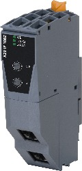
X20IF1082Description:
- POWERLINK for real-time Ethernet communication
- Integrated hub for efficient cabling
- Configurable ring redundancy
The interface module can be used to expand the X20 CPU for specific applications. It is equipped with an POWERLINK interface.
The interface has two RJ45 sockets. Both connections lead to an integrated hub. This makes it easy to create daisy-chain connections using POWERLINK.
Further information:
Technology information: Redundancy
User's manual: Redundancy for control systems
| Automation Studio HW Upgrades | Version (Date) | Download |
|---|---|---|
| V2.7 HW Upgrade (X20IF1082) | EXE / 572 KB | |
| V2.7 HW Upgrade (X20IF1082) | EXE / 1 MB | |
| V3.0 HW Upgrade (X20IF1082) | EXE / 2 MB | |
| V4.0 HW Upgrade (X20IF1082) | EXE / 1 MB |
| Documentation | Version (Date) | Download |
|---|---|---|
| Datasheet X20IF1082 | PDF / 232 KB | |
| Installation- / EMC-Guide | PDF / 20 MB | |
| Redundancy for control systems | PDF / 9 MB | |
| X20 System User´s Manual | PDF / 7 MB |
| E-CAD (Electro or EPLAN Templates) | Version (Date) | Download |
|---|---|---|
| X20 EPLAN P8 from V2.4 | EXE / 160 MB |
| M-CAD (Mechan. Templates) | Version (Date) | Download |
|---|---|---|
| 3D File STEP/DXF X20BC and X20IF Module | ZIP / 1 MB |