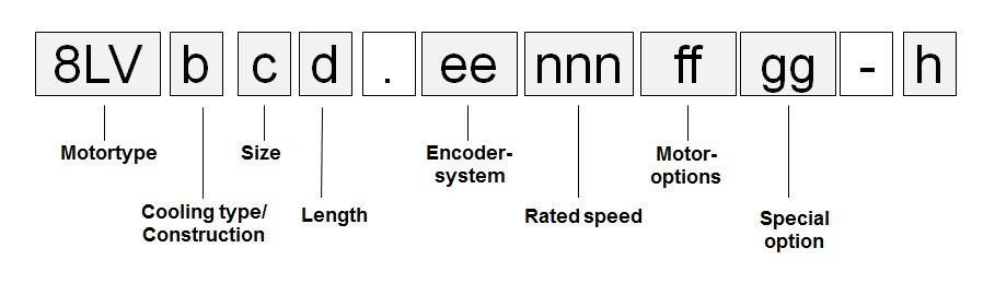
Cooling / construction type (b)
Cooling / construction type (b)
Cooling type A
8LV servo motors are self-cooling and have a long, slim design. The motors must be installed on the cooling surface (flange).
Size and length (c) (d)
Size and length (c) (d)
The 8LV servo motor series is available in three different sizes (1, 2, 3). They have different dimensions (especially flange dimensions) and power ratings. The various sizes can be differentiated by a number (c) in the model number. The larger the number, the larger the flange dimensions and power rating for the respective motor.
Cooling type | Available sizes | ||
|---|---|---|---|
1 | 2 | 3 | |
A | Yes | Yes | Yes |
The 8LV servo motor series is available in two different lengths. They have different power ratings with identical flange dimensions. The various lengths can be differentiated by a number (d) in the model number.
Length | Available sizes | ||
|---|---|---|---|
1 | 2 | 3 | |
2 | --- | Yes | --- |
3 | Yes | Yes | Yes |
Encoder system (ee)
Encoder system (ee)
Resolver
BRX resolvers are used in the servo motors. These resolvers are fed with a single sinusoidal signal (reference signal) and return two sinusoidal signals. The amplitude of these signals change with the angular position (sine or cosine form).
Name | Order code (ee) |
|---|---|
R0 | |
Precision | 10 angular minutes |
Non-linearity | 1 arcminute |
Vibration during operation | ≤ 100 m/s² |
Shock during operation | ≤ 400 m/s² |
EnDat 2.2 encoder
General information
Digital drive systems and position control loops with position measuring devices for determining measurement values require fast and highly secure data transfer from the measurement devices. In addition, other data such as drive-specific characteristics, correction tables, etc. should also be available. To ensure a high level of system security, the measurement devices must be integrated in routines for detecting errors and have the ability to perform diagnostics.
The EnDat interface from HEIDENHAIN is a digital, bidirectional interface for measurement devices. It is able to output position values from incremental and absolute measurement devices and can also read and update information on the measurement device or store new data there. Only 4 signal lines are needed because serial data transfer is used. The data is transferred synchronous to the clock signal defined by the subsequent electronics. The type of transfer used (e.g. for position values, parameters, diagnostics, etc.) is selected using mode commands sent to the measurement device by the subsequent electronics.
Technical data
Name | Order code (ee) |
|---|---|
B1 | |
Encoder type | EnDat multi-turn |
Functionality | Inductive |
EnDat protocol | EnDat 2.2 |
Recognizable revolutions | 65,536 (216) |
Position values per revolution | 262,144 (18-bit) |
Precision | ± 280'' |
Vibration during operation, 55 to 2000 Hz | ≤300 m/s² (IEC 60 068-2-6) |
Shock during operation, 6 ms duration | ≤1000 m/s² (IEC 60 068-2-27) |
Battery lifespan 1) | ≥6 years |
Manufacturer Internet address | Dr. Johannes Heidenhain GmbH www.heidenhain.de |
Manufacturer's product ID | EBI1135 |
| 1) | Battery in the ACOPOS drive |
Rated speed (nnn)
Rated speed (nnn)
The rated speed is listed as part of the model number in the form of a 3-digit code (nnn). This code represents the nominal speed divided by 100 at 80 VDC operation. The respective combination of other motor options is listed in the form of a 2-digit code (ff) as part of the model number.
Size | Available nominal speeds nN [rpm] at 80 VDC operation | ||
|---|---|---|---|
1500 | 2100 | 3000 | |
1 | Yes | --- | Yes |
2 | Yes | --- | Yes |
3 | Yes | Yes | --- |
Oil seal (ff)
Oil seal (ff)
The 8LV servo motors in sizes 2 and 3 are available with an optional Form A oil seal in accordance with DIN 3760. When equipped with an oil seal, the motors have IP65 protection in accordance with EN 60034-5.
Proper lubrication of the oil seal must be guaranteed throughout the entire lifespan of the motor.
Holding brake (ff)
Holding brake (ff)
Servo motors in the 8LV series can be delivered with a holding brake. It is used to hold the motor shaft when no power is applied to the servo motor.
Operating principle
The holding brake is controlled by the ACOPOSmicro servo drive. It uses permanent magnets that are demagnetized when 24 VDC is applied to a magnet winding. This releases the brake.
This brake is designed as a holding brake and is not permitted to be used for operational braking! If used properly, the brake has a lifespan of approximately 5,000,000 cycles (releasing and reengaging the brake again is one cycle).
Loaded braking during an emergency stop is permitted but reduces its service life. The required brake holding torque is determined based on the actual load torque. If not enough information is known about the load torque, it is recommended to assume a safety factor of 2.
Technical data for the standard holding brake
Name | Motor size | ||
|---|---|---|---|
1 | 2 | 3 | |
Holding torque MBr [Nm] | 0.35 | 2.2 | 3.2 |
Connected load Pon [W] | 8 | 8.4 | 13.4 |
Maximum speed nmax [rpm] | 6000 | 12000 | 12000 |
Supply current Ion [A] | 0.33 | 0.35 | 0.56 |
Supply voltage Uon [V] | 24 VDC +6% / -10% | 24 VDC +6% / -10% | 24 VDC +6% / -10% |
Activation delay ton [ms] | 10 | 28 | 29 |
Release delay toff [ms] | 6 | 14 | 19 |
Moment of inertia JBr [kgcm²] | 0.013 | 0.07 | 0.38 |
Mass mBr [kg] | 0.1 | 0.16 | 0.29 |
Shaft end (ff)
Shaft end (ff)
All 8LV servo motor shafts comply to DIN 748. They can be delivered with a smooth shaft or a keyed shaft (depending on motor size).
Smooth shaft
A smooth shaft end is used for a force-fit shaft-hub connection that guarantees a zero-play connection between shaft and hub as well as smooth operation. The end of the shaft has a threaded center hole.
Keyed shaft
The keyed shaft can be used for a form-fit torque transfer with low demands on the shaft-hub connection and for handling torques with a constant direction.
The keyways for the servo motors conform to keyway form N1 according to DIN 6885-1. Form A shaft keys that conform to DIN 6885-1 are used. Motors with keyways are balanced using the half-key convention according to DIN ISO 8821. The end of the shaft has a threaded center hole which can be used to mount drive elements with shaft end disks.
Special motor options (gg)
Special motor options (gg)
00...No special motor options
Motor version (h)
Motor version (h)
The motor version is automatically specified by the configurator and can be seen in the technical data.
Order code motor options (ff)
The respective code (ff) for the order key can be found in the following table:
Motor option | ||||
|---|---|---|---|---|
Connection direction | Oil seal | Holding brake | Shaft end | Code for the order key (ff) |
Angled (swivel connector) | No | No | Smooth | D0 |
No | No | Keyed | D11) | |
No | Yes | Smooth | D2 | |
No | Yes | Keyed | D31) | |
Yes | No | Smooth | D6 | |
Yes | No | Keyed | D71) | |
Yes | Yes | Smooth | D8 | |
Yes | Yes | Keyed | D91) |
| 1) | Not available for size 1. |
Example Order 1
Example Order 1
A three-phase synchronous motor of type 8LVA22 with a nominal speed of 3000 rpm has been selected for an application. The motor should be equipped with a holding brake, a keyed shaft and an EnDat encoder.
The (ee) code for the encoder system is B1.
The (nnn) code for a nominal speed of 3000 rpm is 030.
The (ff) code for the other options is D3.
The model number for the required motor is 8LVA22.B1030D300-0
Example Order 2
Example Order 2
A three-phase synchronous motor of type 8LVA33 with a nominal speed of 1500 rpm has been selected for an application. The motor should be equipped without a holding brake, with a smooth shaft and a resolver encoder. The motor should also be equipped with a oil seal.
The code (ee) for the encoder system is R0.
The code (nnn) for a nominal speed of 1500 rpm is 015.
The (ff) code for the other options is D6.
The model number for the required motor is 8LVA33.R0015D600-0